Support Arm

Inactive Publication Date: 2010-02-18
STICHTING ESCROW TV MOTIONS
View PDF15 Cites 8 Cited by
  • Summary
  • Abstract
  • Description
  • Claims
  • Application Information

AI Technical Summary

Benefits of technology

[0008]It is an object of the invention to provide a support arm which can be manufactured in a simple and inexpensive manner from components which can readily be obtained and modified.
[0009]It is another object of the invention to provide a support arm which can easily be automated.

Problems solved by technology

The arms are not specifically suited for mounting a flat screen to for instance a wall.
Due to their construction, these arms leave a substantial distance between a flat screen and a wall when the arm is in its folded position.
Furthermore, these arms are very difficult to automate.
Full stabilization under heavy loads may prove difficult.
It is difficult to automate the known support arms and they are not stable.
Often, due to the weight in combination with the long arm which causes high torque, backlash will occur after some use.

Method used


Image

  • Support Arm
  • Support Arm
  • Support Arm

Examples


Embodiment Construction

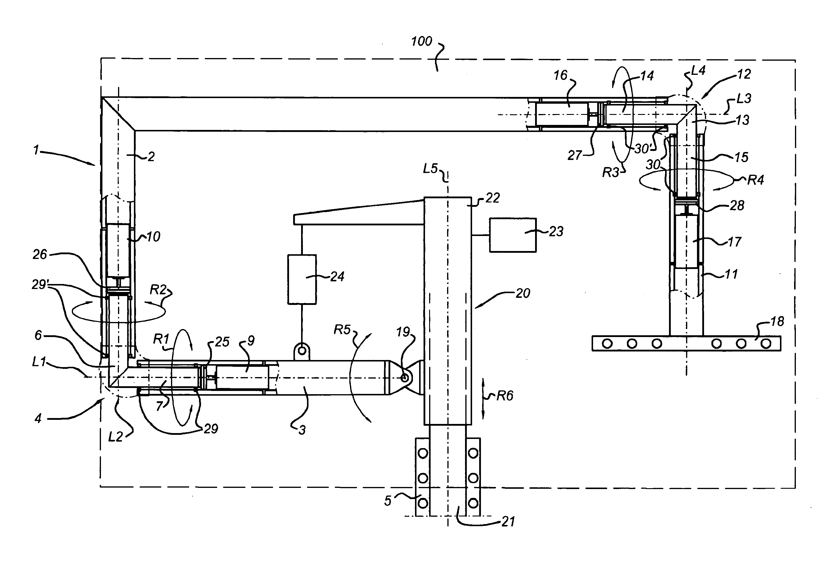
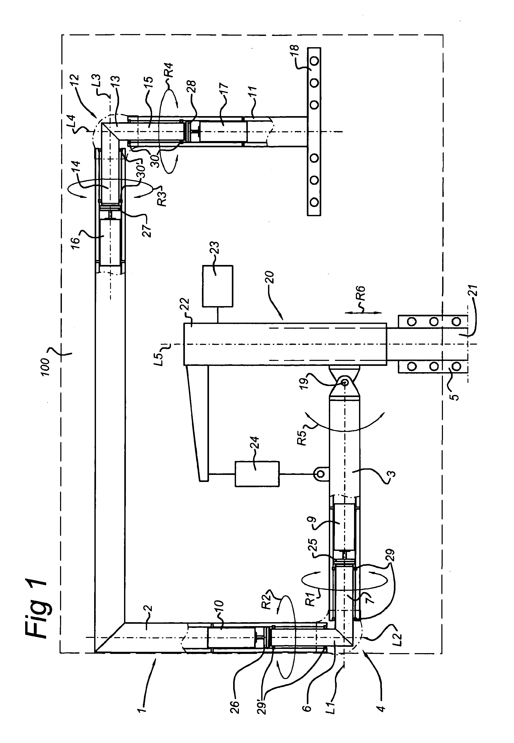
[0056]FIG. 1 shows a support arm 1, which is in this case provided with a flat LCD screen 2 which is indicated by means of dashed lines. The support arm 1 is provided with a first member 3 and a second member 2, which have a first longitudinal axis L1 and a second longitudinal axis L2, respectively. The first member 3 and the second member 2 are coupled to one another by means of two rotation joints 4, which connect the two members 3, 2 at an angle. The members 2, 3 are in this case connected at an essentially right angle. The first member 3 is coupled to a fastening part 5, in this case a fastening part for attaching the arm 1 on or against a wall. Alternatively, the support arm may also be attached to a floor or on or in a piece of furniture. A fastening part will be adapted to such a construction. For a person skilled in the art, the design of such a fastening part is simple. The members in this description are preferably round tubes.

[0057]The first pair of joints 4, which connec...


PUM


Abstract

The invention relates to a support arm for an apparatus, preferably for a display screen, comprising a first fastening part for attaching the support arm to a frame or a wall, a first member, at one end coupled to the first fastening part and at another end coupled to a first pivot joint which makes rotation about a first axis of rotation possible, a second member which, at a first end, is coupled to the first pivot joint, and, at a second end, is provided with a second pivot joint which makes rotation about a second axis of rotation possible, a second fastening part for attaching the apparatus to the support arm, which second fastening part is coupled to the second pivot joint, the first and second axes of rotation essentially being parallel to one another.

Description

BACKGROUND OF THE INVENTION[0001]The invention relates to a support arm for an apparatus, preferably a display screen, specifically a flat display screen. The invention furthermore relates to a pivot joint, in particular suitable for a support arm.[0002]Such a support arm is known from EP-A2-1.312.852 and GB-2.416.062, for instance. These arms have a first member which is pivotally connected to a second member. The arms are not specifically suited for mounting a flat screen to for instance a wall. Due to their construction, these arms leave a substantial distance between a flat screen and a wall when the arm is in its folded position.[0003]Another arm is disclosed in U.S. Pat. No. 5,321,579. In its folded position, this arm is very flat, holding a flat screen almost against a wall. This arm, however, needs to be mounted underneath a flat screen of flat panel display.[0004]U.S. Pat. No. 4,170,336 discloses a suspension arm for an operating room microscope. These microscopes are not v...

Claims


Application Information

Patent Timeline
IPC IPC(8): A47B96/07F16H55/17
CPCF16M11/10F16M11/12F16M11/18Y10T74/19888F16M11/24F16M13/02F16M2200/041F16M11/2014
Inventor STOELINGA, DIRK JAN
Owner STICHTING ESCROW TV MOTIONS
Why Eureka
Try Eureka