Rotor and permanent-magnet rotating electrical machine
a technology of rotating electrical machines and permanent magnets, which is applied in the direction of dynamo-electric machines, electrical apparatus, magnetic circuits characterised by magnetic materials, etc., can solve the problems of deteriorating the performance of rotating electrical machines, insufficient to suppress eddy current or prevent problems such as deterioration, to prevent a temperature increase of permanent magnets, prevent a characteristic deterioration of permanent magnets, and suppress the generation of eddy currents
- Summary
- Abstract
- Description
- Claims
- Application Information
AI Technical Summary
Benefits of technology
Problems solved by technology
Method used
Image
Examples
first embodiment
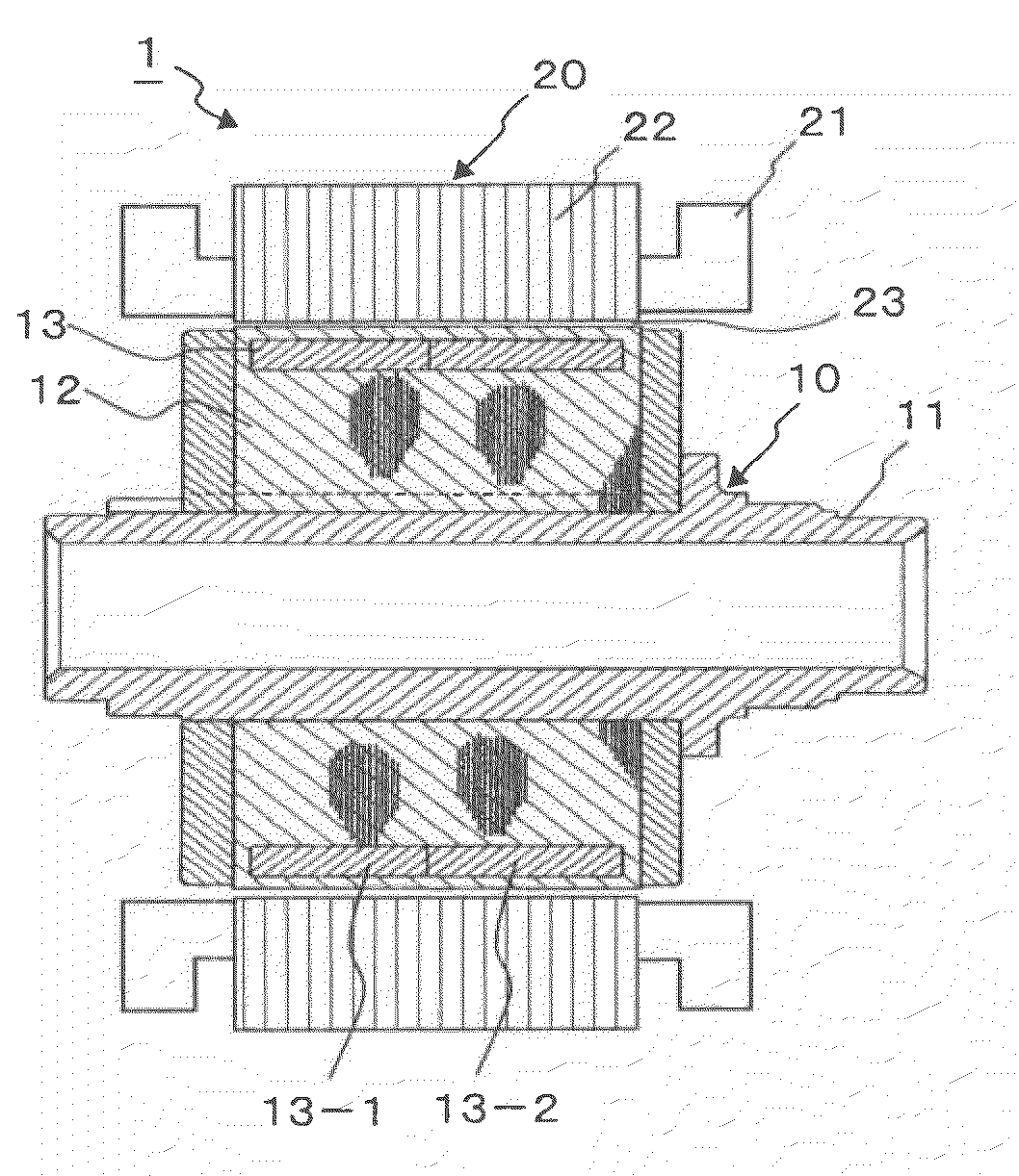
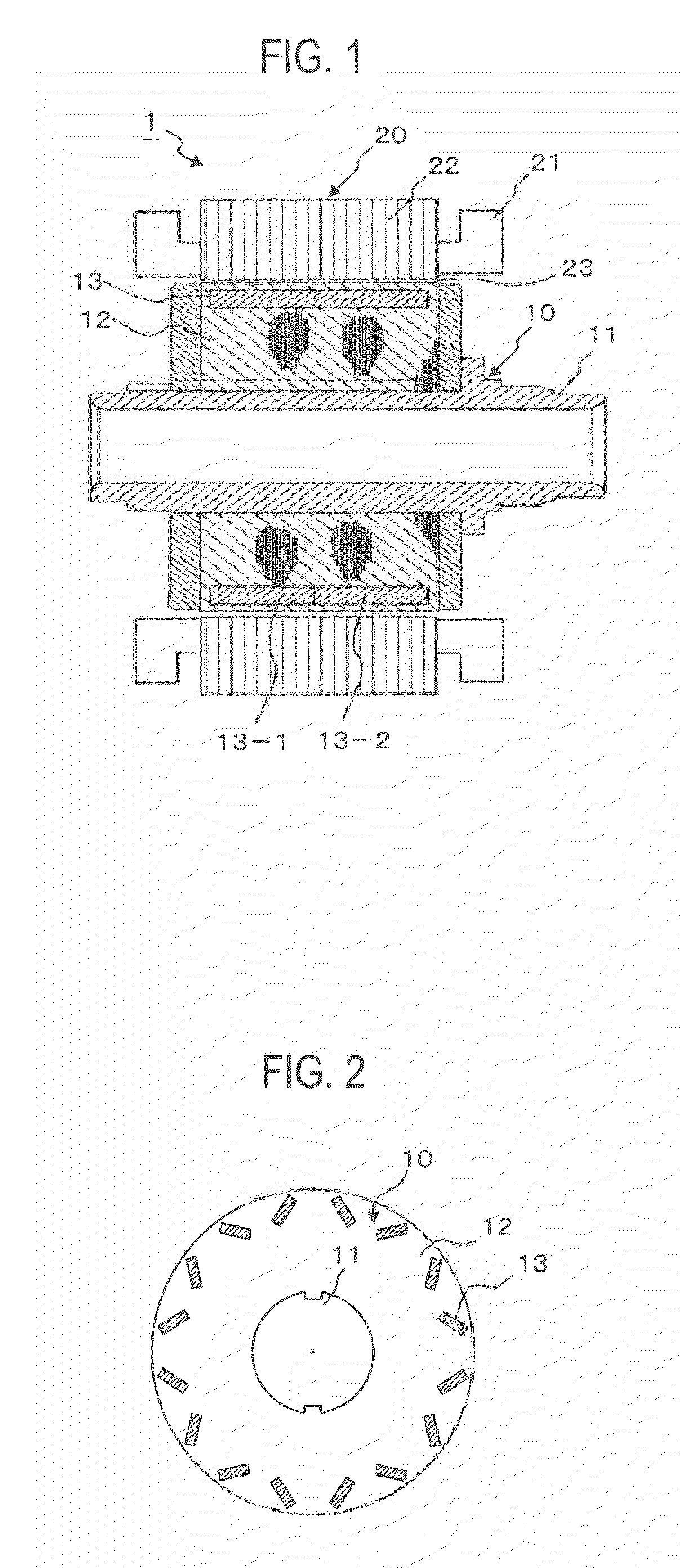
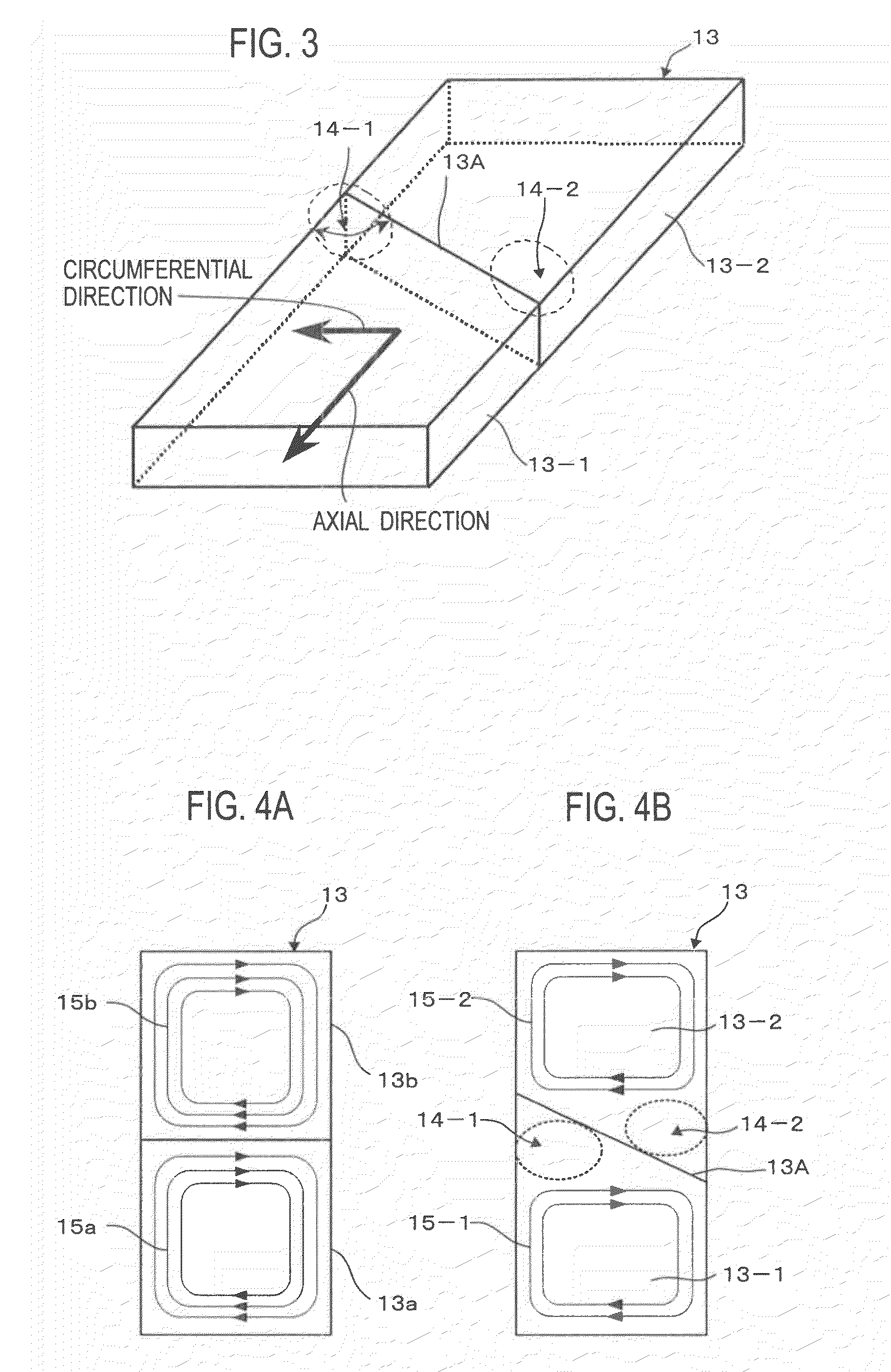
[0033]With reference to FIGS. 1 to 5, a rotor 10 and a permanent-magnet rotating electrical machine 1 incorporating the rotor according to the first embodiment of the present invention will be explained. The permanent-magnet rotating electrical machine 1 according to the first embodiment is an interior permanent-magnet rotating electrical machine (IPM). The rotor 10 of the permanent-magnet rotating electrical machine 1 has a rotor core 12. Permanent magnets 13 are embedded in the rotor core 12 on the outer circumferential side thereof. A stator 20 of the permanent-magnet rotating electrical machine 1 is arranged outside the rotor 10, to face the rotor 10 with an air gap 23 interposing between them. The stator 20 is composed of a stator core 22 and a stator coil 21 wound around the stator core 22. The structure of the stator 20 is not particularly limited and can be any standard structure.
[0034]When the rotor 10 is of an inner rotor type, it is arranged inside the stator 20 having th...
second embodiment
[0039]With reference to FIG. 5, a permanent-magnet rotating electrical machine and rotor according to the second embodiment of the present invention will be explained. This embodiment is characterized by a dividing method of a permanent magnet 13 arranged in the rotor 10. Except the dividing method of the permanent magnet 13, this embodiment is the same as the first embodiment.
[0040]The permanent magnet 13 is divided into three segments 13-1, 13-2, and 13-3 with two dividing faces 13A and 13B that obliquely cross an axial direction. The dividing faces 13A and 13B each are a single plane. The dividing faces 13A and 13B of the permanent magnet 13 and an end face of the permanent magnet 13 facing a circumferential direction form acute angles to define narrowed areas 14-1, 14-2, 14-3, and 14-4.
[0041]In the rotor 10 according to the embodiment, the segments 13-1, 13-2, and 13-3 of the permanent magnet 13 have the narrowed areas 14-1 to 14-4 to obstruct eddy currents and suppress the gene...
third embodiment
[0043]With reference to FIG. 7, a permanent-magnet rotating electrical machine and rotor according to the third embodiment of the present invention will be explained. The structures of the rotating electrical machine 1 and rotor 10 of this embodiment are similar to those of the first embodiment except a dividing method of the permanent magnet 13.
[0044]As illustrated in FIG. 7, the permanent magnet 13 in the rotor 10 according to the embodiment is divided into a plurality of segments 13-1 and 13-2 in an axial direction with a dividing face 13A that consists of a plurality of flat faces repeatedly forming ridges and valleys. The dividing face 13A of the permanent magnet 13 and an end face of the permanent magnet 13 facing a circumferential direction form acute angles to define narrowed areas 14-1 and 14-2.
[0045]In the rotor 10 according to the embodiment, the permanent magnet 13 has the narrowed areas 14-1 and 14-2, to suppress the generation of eddy currents and prevent the temperatu...
PUM
 Abstract
Description
Claims
Application Information
 - R&D
- Intellectual Property
- Life Sciences
- Materials
- Tech Scout
- Unparalleled Data Quality
- Higher Quality Content
- 60% Fewer Hallucinations
Browse by: Latest US Patents, China's latest patents, Technical Efficacy Thesaurus, Application Domain, Technology Topic, Popular Technical Reports.
© 2025 PatSnap. All rights reserved.Legal|Privacy policy|Modern Slavery Act Transparency Statement|Sitemap|About US| Contact US: help@patsnap.com


