
Magnetic membrane mirror

a magnetic membrane mirror and mirror technology, applied in the field of deformable mirrors, can solve the problems of reducing system throughput and contrast, difficult and expensive fabrication of deformable mirrors such as those used in high-performance adaptive optics systems of major observatories, and reducing the throughput of the system

Inactive Publication Date: 2010-02-04
MASSACHUSETTS INST OF TECH
View PDF7 Cites 16 Cited by
  • Summary
  • Abstract
  • Description
  • Claims
  • Application Information

AI Technical Summary

Benefits of technology

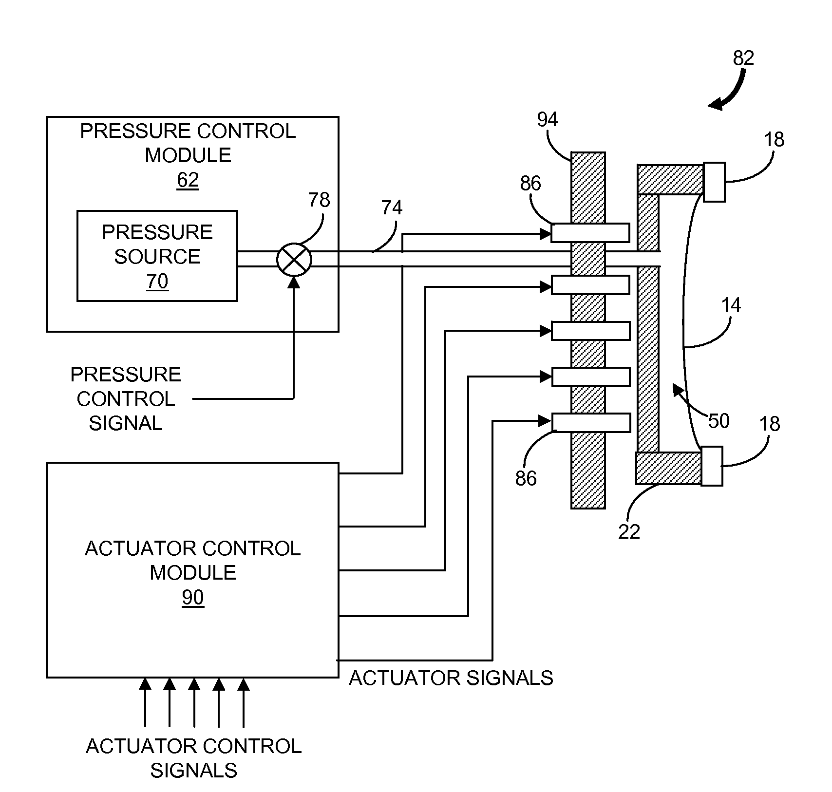
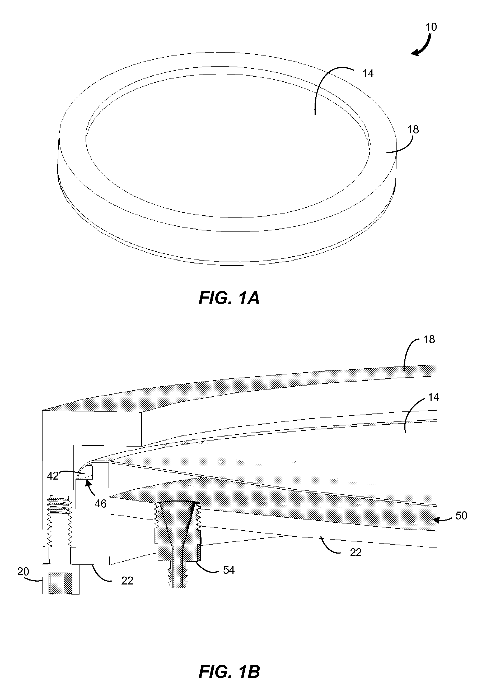
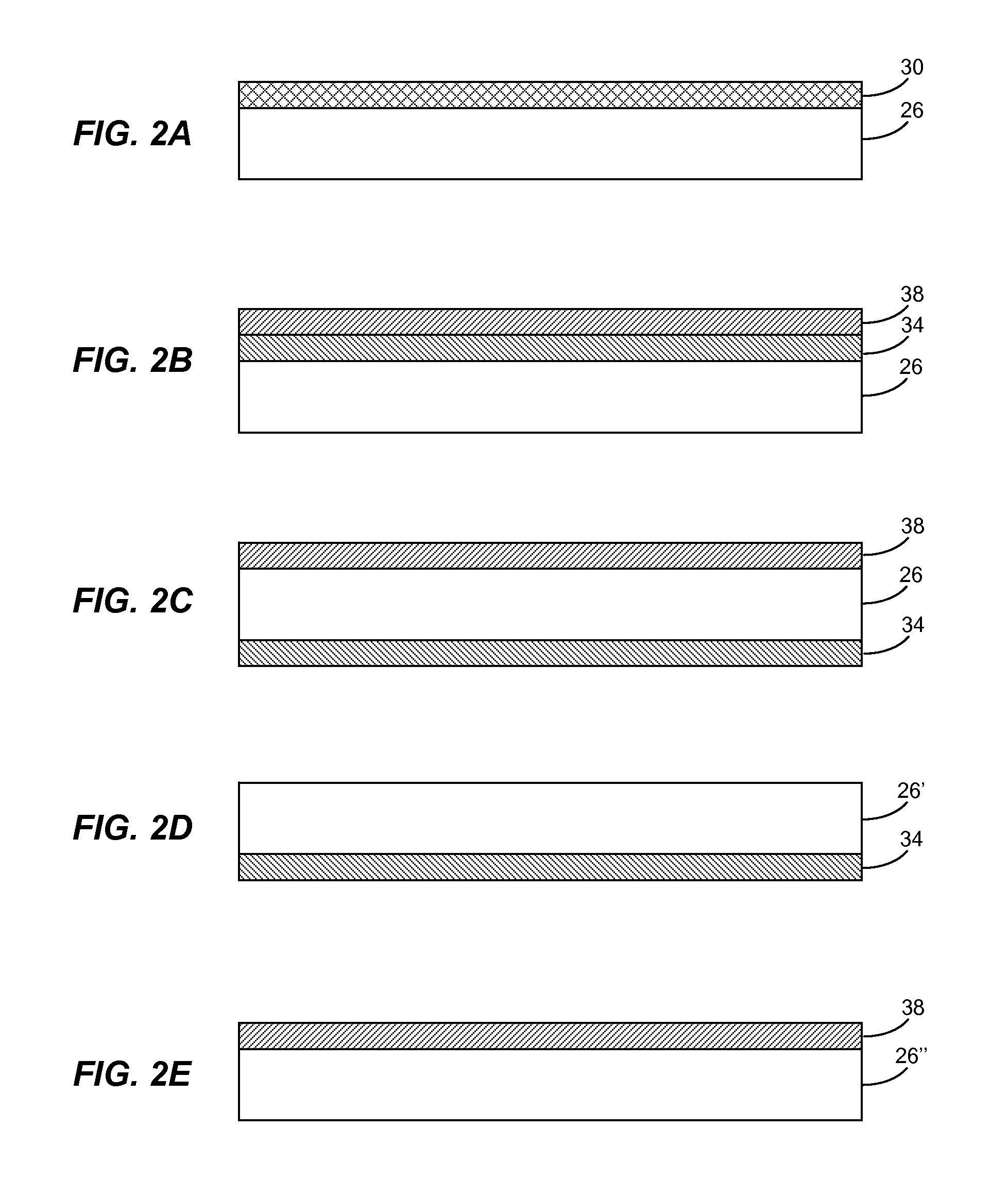
The invention is a magnetic membrane mirror that includes a reflective flexible membrane and a frame. The reflective flexible membrane comprises a magnetic material and the frame has a mounting surface and an opening. The reflective flexible membrane is secured over the mounting surface to define an enclosed volume between the frame and the reflective flexible membrane. The opening in the frame is adapted for pressure control of the enclosed volume, wherein the shape of a surface of the reflective flexible membrane is determine according to a transmembrane pressure. The invention also features a method for adjusting a mirror surface of a magnetic membrane mirror and a method for fabricating a magnetic membrane mirror. Additionally, the invention includes an optical system that includes a magnetic membrane mirror, a wavefront sensor, and an actuator control module. The actuator control module controls the electromagnetic actuators to dynamically deform the surface in response to wavefront data generated by the wavefront sensor. The technical effects of the invention include improved optical performance and control of the mirror surface for wavefront correction.

Problems solved by technology

The design and fabrication of flexible mirrors remains one of the greatest challenges in the field of astronomical-telescope engineering, due in large part to the conflict between the rigidity necessary for the mirror to hold a precise optical surface and the flexibility required to perform wavefront correction.
Deformable mirrors such as those used in high-performance adaptive-optics systems of major observatories are difficult to fabricate and expensive.
Moreover, difficulties associated with fabricating curved deformable mirrors generally means that adaptive-optics systems use a flat deformable mirror as an additional optical component in the optical path of a static imaging system.
The additional optical surface of the deformable mirror increases the scattered light and absorptive light-loss, resulting in a decrease in the system throughput and contrast.
The stiffness of deformable mirrors made from solid substrates limits the actuator density-stroke product, making the fabrication of mirrors with large strokes and high actuator densities challenging.

Method used


Image

  • Magnetic membrane mirror
  • Magnetic membrane mirror
  • Magnetic membrane mirror

Examples


Embodiment Construction

[0018]In brief overview, the invention relates to a magnetic membrane mirror having a flexible membrane comprising a magnetic material and having a high reflectance. The flexible membrane is secured over a frame to enclose a volume between the frame and membrane. A transmembrane pressure is established to achieve a desired mirror shape or curvature. The curvature can be changed by modifying the transmembrane pressure, for example, by increasing or decreasing the pressure in the enclosed volume. An array of electromagnetic actuators generates individually-controlled magnetic fields to cause localized displacements of the mirror surface. The magnetic membrane mirror can be constructed with inexpensive components and can be used as a dynamic component in an adaptive optical system. For example, the magnetic membrane mirror can be employed as the primary mirror in a telescope system employing dynamic correction for atmospheric turbulence.

[0019]FIG. 1A shows a perspective view of a magne...


PUM

PropertyMeasurementUnit
flexibleaaaaaaaaaa
thicknessaaaaaaaaaa
reflective flexibleaaaaaaaaaa

Abstract

Described is a magnetic membrane mirror having a flexible membrane comprising a magnetic material and having a high reflectance. The flexible membrane is secured over a frame to enclose a volume between the frame and membrane. A transmembrane pressure is established to achieve a desired mirror shape or curvature. Curvature can be changed by modifying the transmembrane pressure by increasing or decreasing the pressure in the enclosed volume. An array of electromagnetic actuators generates individually-controlled magnetic fields to cause localized displacements of the mirror surface. The magnetic membrane mirror can be constructed with inexpensive components and can be used as a dynamic component in an adaptive optical system.

Description

RELATED APPLICATION[0001]This application claims the benefit of the earlier filing date of U.S. Provisional Patent Application Ser. No. 60 / 799,452, filed May 11, 2006, titled “Magnetic-Membrane Mirror,” the entirety of which is incorporated herein by reference.GOVERNMENT RIGHTS IN THE INVENTION[0002]This invention was made with United States government support under Contract No. FA8721-05-C-0002 awarded by the United States Air Force. The government may have certain rights in the invention.FIELD OF THE INVENTION[0003]The present invention relates generally to deformable mirrors. More particularly, the invention relates to a magnetic membrane mirror having a mirror surface shape controlled by a transmembrane pressure and electromagnetic actuators.BACKGROUND OF THE INVENTION[0004]High-resolution imaging of celestial objects through the atmosphere and the interstellar medium requires that the wavefront distortion caused by these media be removed before the light from the object reaches...

Claims


Application Information

Patent Timeline
Patent Type & Authority Applications(United States)
IPC IPC(8): G02B7/188B29C65/78
CPCG02B26/0825
Inventor ANGEL, MATTHEW M.
Owner MASSACHUSETTS INST OF TECH
Learn More