
Solar energy collecting and storing system

a solar energy and storage system technology, applied in lighting and heating devices, lighting types, greenhouse gas reduction, etc., can solve the problems of solar systems that fail to normally provide thermal energy to thermal power generators and/or indoor heating devices, and the conventional solar system still has some drawbacks, so as to reduce the influence of light exposure amoun

Inactive Publication Date: 2010-02-04
CHIU HAN CHIEH +3
View PDF23 Cites 9 Cited by
  • Summary
  • Abstract
  • Description
  • Claims
  • Application Information

AI Technical Summary

Benefits of technology

[0005]It is an object of the present invention to provide a solar energy collecting and storing system for converting solar energy into thermal energy. The thermal energy is stored in a heat reservoir. If necessary, the stored thermal energy could be used in a thermal power generator and / or an indoor heating device at any time. In other words, the influence of light exposure amount is reduced.

Problems solved by technology

The conventional solar systems, however, still have some drawbacks.
In a cloudy day or a rainy day, the solar systems fail to normally provide thermal energy to the thermal power generator and / or an indoor heating device.

Method used


Image

  • Solar energy collecting and storing system
  • Solar energy collecting and storing system
  • Solar energy collecting and storing system

Examples


Embodiment Construction

[0015]The present invention will now be described more specifically with reference to the following embodiments. It is to be noted that the following descriptions of preferred embodiments of this invention are presented herein for purpose of illustration and description only. It is not intended to be exhaustive or to be limited to the precise form disclosed.

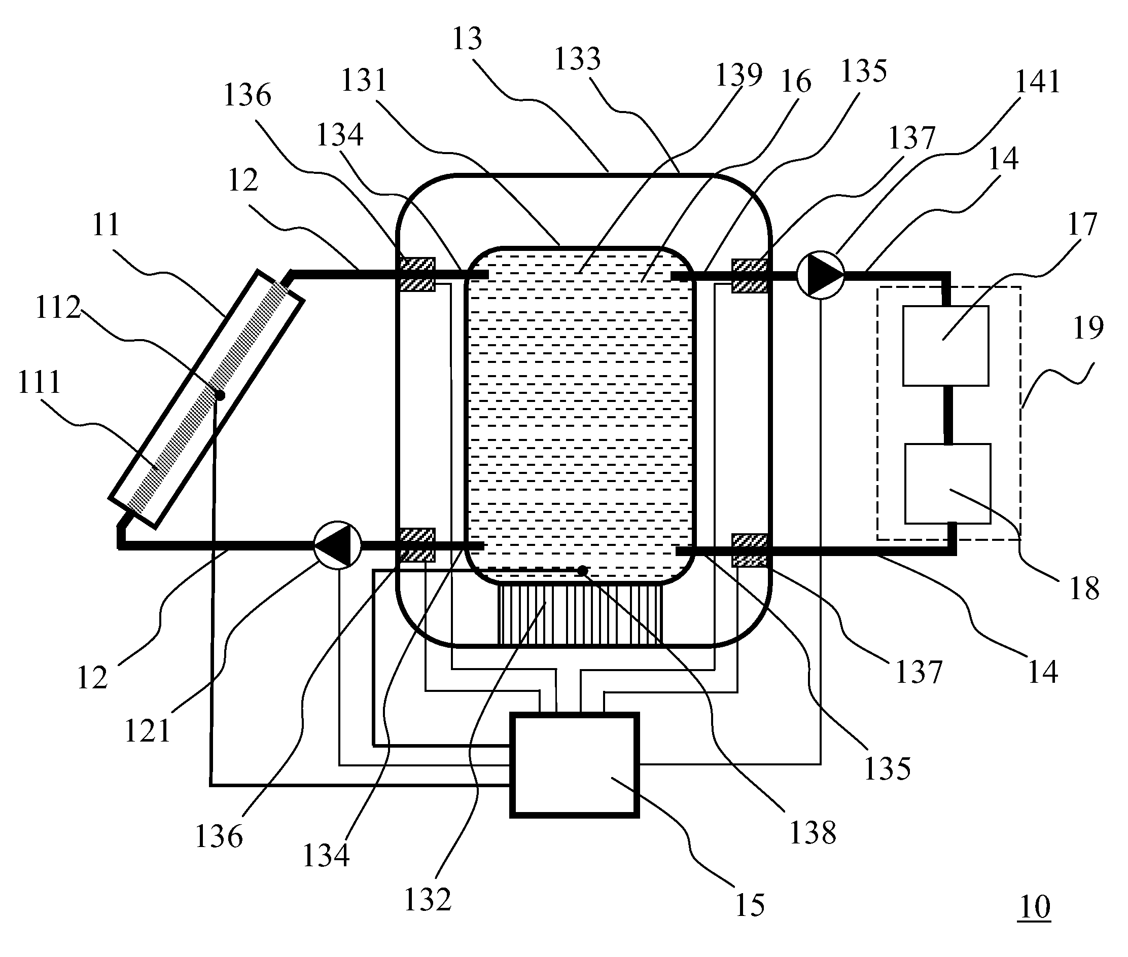
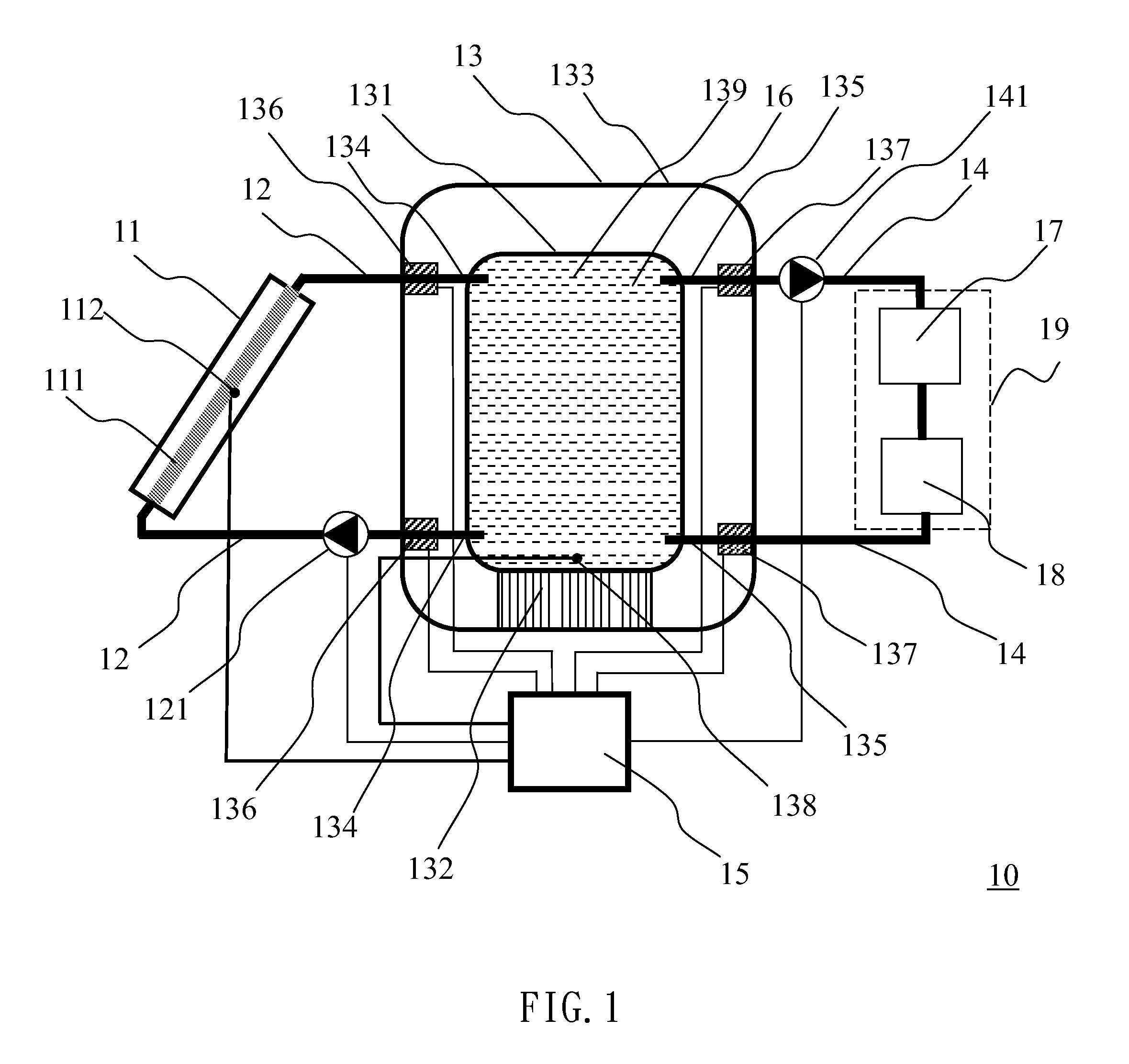
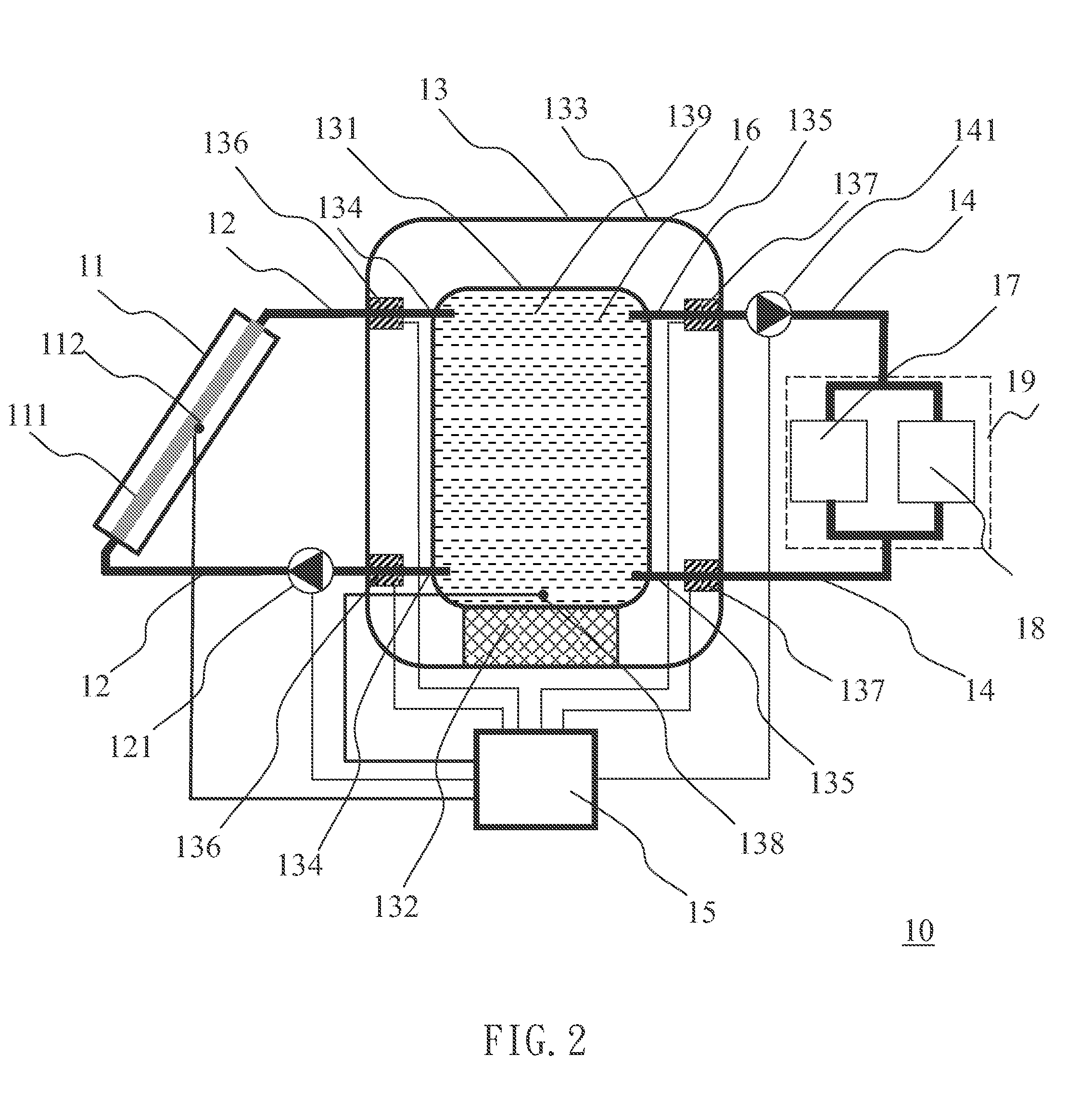
[0016]FIG. 1 is a schematic diagram illustrating the architecture of a solar energy collecting and storing system according to a first preferred embodiment of the present invention. As shown in FIG. 1, the solar energy collecting and storing system 10 comprises a solar energy collecting unit 11, a thermal energy input piping line 12, a heat reservoir 13, a thermal energy output piping line 14, a controller 15 and a working fluid 16. The solar energy collecting unit 11 includes a thermal energy collector 111 and a thermal energy collector temperature sensor 112. A thermal energy input pump 121 is arranged in the thermal energy inp...


PUM


Abstract

A solar energy collecting and storing system includes a solar energy collecting unit and a heat reservoir. By the thermal energy collector, solar light is absorbed and converted into thermal energy for heating a working fluid contained in the thermal energy collector. Multiple input / output control valves and multiple input / output joints are connected with the heat reservoir for controlling the working fluid to flow into or out of the heat reservoir. If the light exposure is insufficient, the input control valve is closed and the heat reservoir is maintained in a thermally isolated state. For utilizing the thermal energy, the output control valve is opened and thus the thermal energy contained in the working fluid is transferred to the thermal energy application device through the thermal energy output piping line.

Description

FIELD OF THE INVENTION[0001]The present invention relates to a solar energy collecting and storing system, and more particularly to a solar energy collecting and storing system for converting solar energy into thermal energy, which is used in a thermal power generator and / or an indoor heating device if necessary.BACKGROUND OF THE INVENTION[0002]Recently, the ecological problems resulted from fossil fuels such as petroleum and coal have been greatly aware all over the world. Consequently, there are growing demands on clean energy. Among various alternative energy sources, solar energy is expected to replace fossil fuel as a new energy source because it provides clean energy without depletion. A conventional solar system has a thermal energy collector for converting solar energy into thermal energy, which is used in a hot-water heater, a thermal power generator and / or an indoor heating device if necessary. In other words, after the solar energy is converted into thermal energy by the ...

Claims


Application Information

Patent Timeline
IPC IPC(8): F24J2/04F24D18/00F24S90/00
CPCF24D11/003F24D2200/14F24H2240/00F28D20/0034Y02B10/20Y02E60/142Y02E70/30F24D2220/08F24H2240/122F24D2220/20Y02E60/14F24D18/00F24D2101/80
Inventor CHIU, HAN-CHIEHJANG, JER-HUANYEH, HUNG-WEIWANG, CHIA-CHI
Owner CHIU HAN CHIEH
Learn More