
Low speed valveless horizontally opposed piston rotary internal combustion engine

a technology of internal combustion engine and piston rotor, which is applied in the direction of combustion engine, internal combustion piston engine, machine/engine, etc., can solve the problems of inefficient, inefficient, and low torque of the very low engine at the low or high end of the operation, and achieves low cost, low cost, and reduced operational reliability.

Inactive Publication Date: 2010-02-04
SPARLING JAMES DOUGLAS
View PDF1 Cites 5 Cited by
  • Summary
  • Abstract
  • Description
  • Claims
  • Application Information

AI Technical Summary

Benefits of technology

[0034]Additional objects and advantages of the invention is that the design diameter of the engine can be decreased or increased to decrease or increase torque output as required by any specific request for amending engine size and torque output.
[0052]Additional objects and advantages of the invention is the elimination of poppet type valves or other valving devices that have many moving parts, need lubrication and can fail which causes the engine to have lower operational reliability than the invention which has a valveless design for both the intake and exhaust gas flows.

Problems solved by technology

Therefore, any prior art engines that produce very low engine torque either at the low or high end of their operation have not kept pace with the industry demands.
Particularly so when torque is produced at the inordinate expense of high engine revolutions.
More so, the torque output of patented engines whereby the pistons rotate along a longitudinal threaded shaft are glaring cases of even more inefficient designs in that the effective crank arm dimension would be one half the diameter of the threaded shaft, these examples being: U.S. Pat. No. 4,554,787, Nov. 26, 1985; U.S. Pat. No. 5,622,142, Apr. 22, 1997; U.S. Pat. No. 5,850,810, Dec. 22, 1998 and U.S. Pat. No. 6,125,819, Oct. 3, 2000.
Further, the continual mechanical piston stresses on a threaded shaft engine are enormous which are not only subject to early wear and malfunctions, it is also obvious that any shaft that penetrates the central portion of a reciprocating piston is also subject to substantial internal pressure losses, something that was epidemic for the Wankel engine, one of the main reasons for its commercial demise.
(a) First is the fact that an engine that has high revolutions is a dead giveaway that it has low torque capabilities.
Although the Wankel was essentially a blip on the radar screen, it did have some limited commercialization with the Japanese automobile market.
Thereafter, it experienced a long series of technical problems in that it was essentially an amalgam of a piston and a turbine engine, so in terms of increased engine revolutions, the Wankel went completely in the wrong direction.
Fuel consumption during high engine revolutions is an obvious deficit that needs no elaboration.
(c) Lubrication becomes critical when all of the internal engine parts are moving with great speed and under high temperature and any interruption in the numerous lubrication locations within the machine spells an early engine failure which is both dangerous and very expensive to repair.
(e) Engine vibrations become a major problem at high revolutions and in most cases, most large aircraft reciprocating engines have very heavy dynamic engine vibration dampeners as part of the main crankshaft.
(f) Mechanical reliability is the bottom line and it is seriously deteriorated by lubrication failures and independent part malfunctions, something that was common with the Wankel.
Engines patented after 1945, for example, had to have come up with a weight to horsepower ratio greater than 1:1 or they could not be considered as viable prior art examples.
Particularly so when it is clear that the torque output of conventional piston engines during the idle range is virtually nil.
Patented horizontally opposed piston engines that have effective crank arms less than the conventional piston engine are even less powerful when it comes to the modern torque output standard of measurement.
There are examples of prior art examples in this subclass where there are two power strokes per for each movement of the piston which seems to be the most effective limitation for those designs, however, when compared to the subaverage torque performances, particularly during the idle range, the net result is a range of prior art engines that have clearly not surpassed the standards of the conventional reciprocating piston engine.
Further, should the number of power strokes be very high in the prior art engines, particularly during high power settings, the problems caused by the combustion particulates and other ozone causing discharges are also disregarded by the abstracts and the patent drawings.
Clearly, the gas turbine would not operate as designed.
Reviewing the specific mechanical aspects of the forty three prior art examples, it is most evident that virtually all of the mechanical parts under review are simply not capable of being quickly formed on a punch press machine, something that increases the initial and repair costs significantly.

Method used


Image

  • Low speed valveless horizontally opposed piston rotary internal combustion engine
  • Low speed valveless horizontally opposed piston rotary internal combustion engine
  • Low speed valveless horizontally opposed piston rotary internal combustion engine

Examples


Embodiment Construction

[0421]Before explaining the present invention in detail, it is to be understood that the present invention is not limited or restricted in any way in it application or uses relative to the details of construction and arrangement of parts as illustrated by the accompanying drawings, because the present invention is capable of other embodiments and variations and of being produced or carried out in various ways. Furthermore, it is to be understood that the phraseology or terminology employed here is for the purpose of description and illustration only, and not for the purpose of limitation or restriction. Further still, discussions of mechanical dimensions, angles and other various operative descriptive terms are for illustration only and are not for the purpose of limitation or restriction.

[0422]As an extended preliminary statement, the detailed description of the invention and its various operational characteristics reflects the stated preferred embodiments which will now follow, ho...


PUM


Abstract

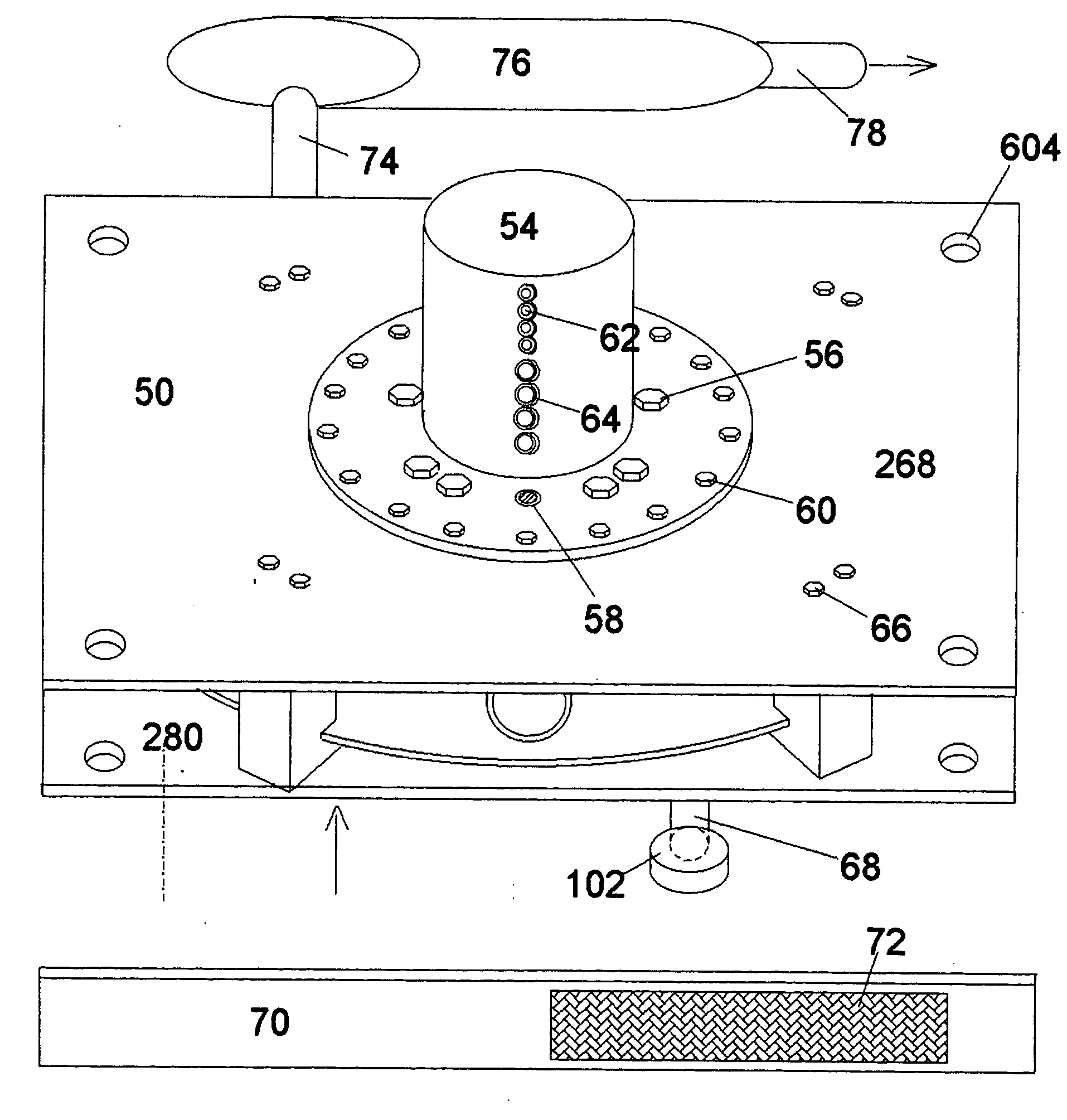
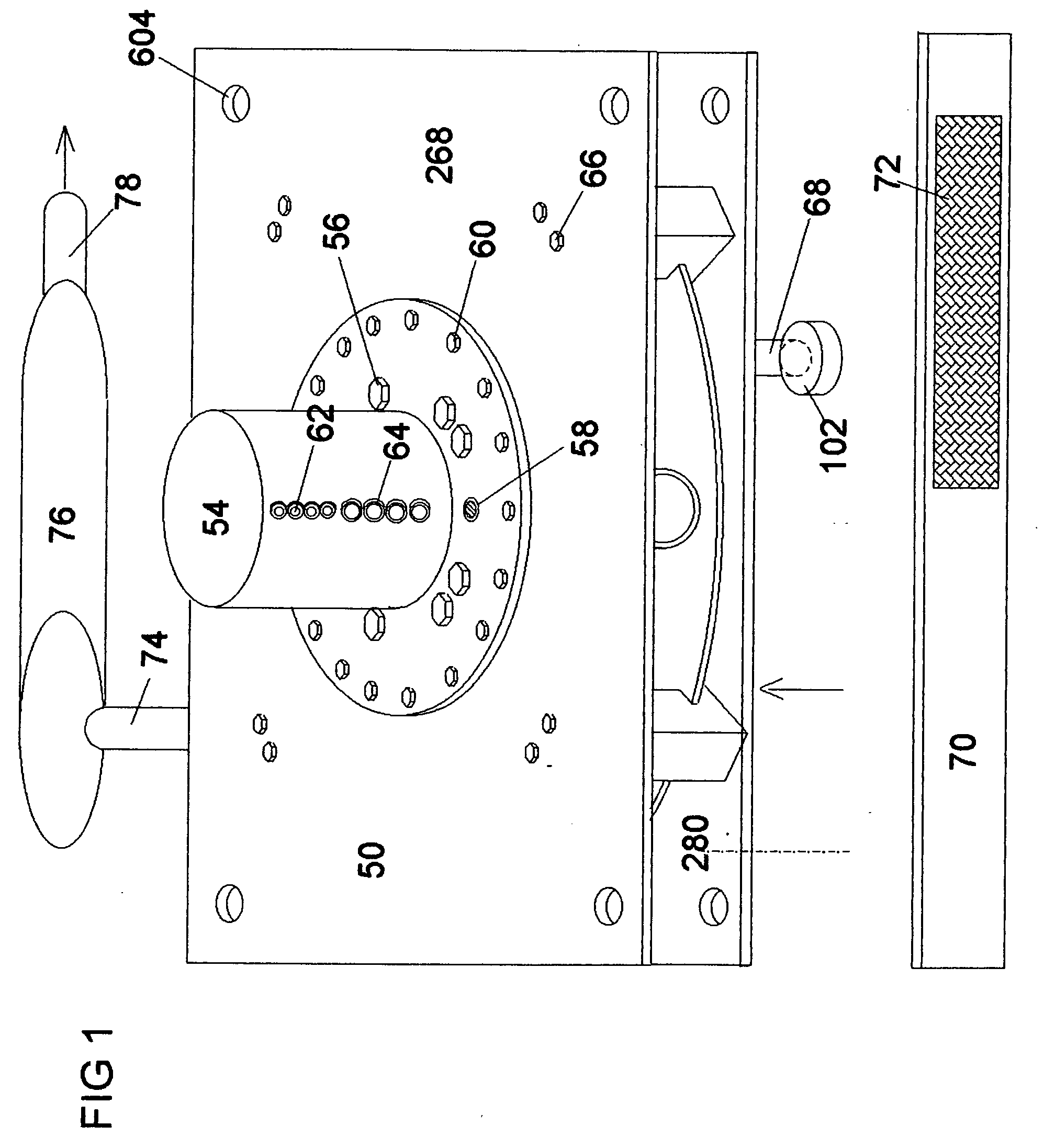
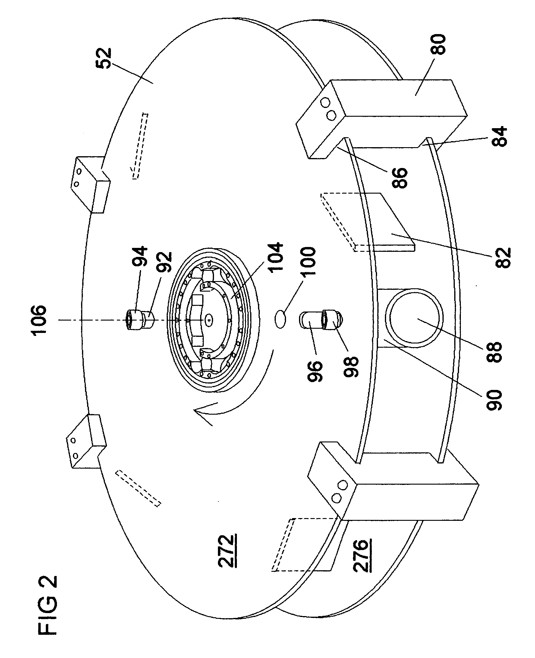
Presented is a very low speed, high torque, horizontally opposed, rotary, valveless, Otto cycle piston engine producing four power strokes per revolution, the engine consisting of a fixed engine case assembly having upper and lower plates, the engine rotor assembly having upper and lower plates, sandwiching a single, closed ended cylinder assembly, the cylinder containing intake and exhaust-intake ports, independently reciprocating power and head pistons, each piston being reciprocally controlled by its vertically projecting piston bearing sets contacting respective sets of upper and lower, inner and outer peripheral cam plates, the engine being thus rotated, the cylinder being lubricated by a sealed, recirculating air-oil mist system, the engine rotor assembly having a lower, vertically projecting gear box housing containing a gas porting cap, a vertical drive shaft, two counter rotating output shafts, intake and exhaust pipes, and an exhaust gas filter canister.

Description

CROSS-REFERENCE TO RELATED APPLICATIONS[0001]Not applicableFEDERALLY SPONSORED RESEARCH[0002]Not applicable.SEQUENCE LISTING OR PROGRAM[0003]Not applicable.BACKGROUNDField of Invention[0004]The invention relates to a low speed valveless horizontally opposed piston rotary internal combustion engine, the power piston and head pistons moving independently, each being controlled by a set of upper and lower outer peripheral power piston cam plates and upper and lower inner peripheral head piston cam plates, the inward motion of the pistons controlled by the slopes of the cams. A single, closed ended rotating piston houses the axially disposed pistons while internal cylinder compartments provide exhaust-intake port cooling air, and provides for the creation and recirculation of air-oil mist which is recirculated between the power piston and head piston and mid barrel assembly which has internal passages for the lubrication system.BACKGROUND OF THE INVENTION[0005]The invention is a truly s...

Claims


Application Information

Patent Timeline
IPC IPC(8): F02B53/00
CPCF02B57/10F02B57/06
Inventor SPARLING, JAMES DOUGLAS
Owner SPARLING JAMES DOUGLAS
Learn More