
Simultaneous detection apparatus of raman and light scattering

a technology of light scattering and simultaneous detection, which is applied in the direction of optical radiation measurement, instruments, spectrometry/spectrophotometry/monochromators, etc., can solve the problems of inability to simultaneously detect the size and shape of the molecular environment, the difficulty of adjusting the light source if necessary, and the inability of prior arts to simultaneously analyze information

Active Publication Date: 2010-01-28
SEOUL NAT UNIV R&DB FOUND
View PDF5 Cites 33 Cited by
  • Summary
  • Abstract
  • Description
  • Claims
  • Application Information

AI Technical Summary

Benefits of technology

The present invention is a simultaneous detection apparatus of Raman and light scattering, which can detect changes in the size and molecular environment of molecules in a sample. This allows for the analysis of information on the size and shape of the sample, as well as the molecules that make up the sample. The apparatus can detect both the elastic and inelastic light scattering, and can easily alter the light sources to study changes in the molecular environment. The technical effect of the invention is the ability to simultaneously detect and analyze information on the size and molecular structure of a sample.

Problems solved by technology

Thus, when an environment of molecules constituting an object material are changed according to changes of the object material in size and shape, the changes of the molecular environment, and its size and shape can not be simultaneously detected.
The prior arts have problems in that, in order to study such phenomena, both detection apparatuses for Raman scattering and light scattering should be equipped at the same time, and light sources thereof are difficult to be altered, if necessary.
That is, the prior arts have difficulty in simultaneously analyzing information such as chemical characteristics of components according to the kinds of samples, environmental changes, sizes and shapes of the components around the sample.

Method used


Image

  • Simultaneous detection apparatus of raman and light scattering
  • Simultaneous detection apparatus of raman and light scattering
  • Simultaneous detection apparatus of raman and light scattering

Examples


exemplary embodiment 1

Raman Scattering Detection in 180° Geometry and Light Scattering Detection in 90° Geometry

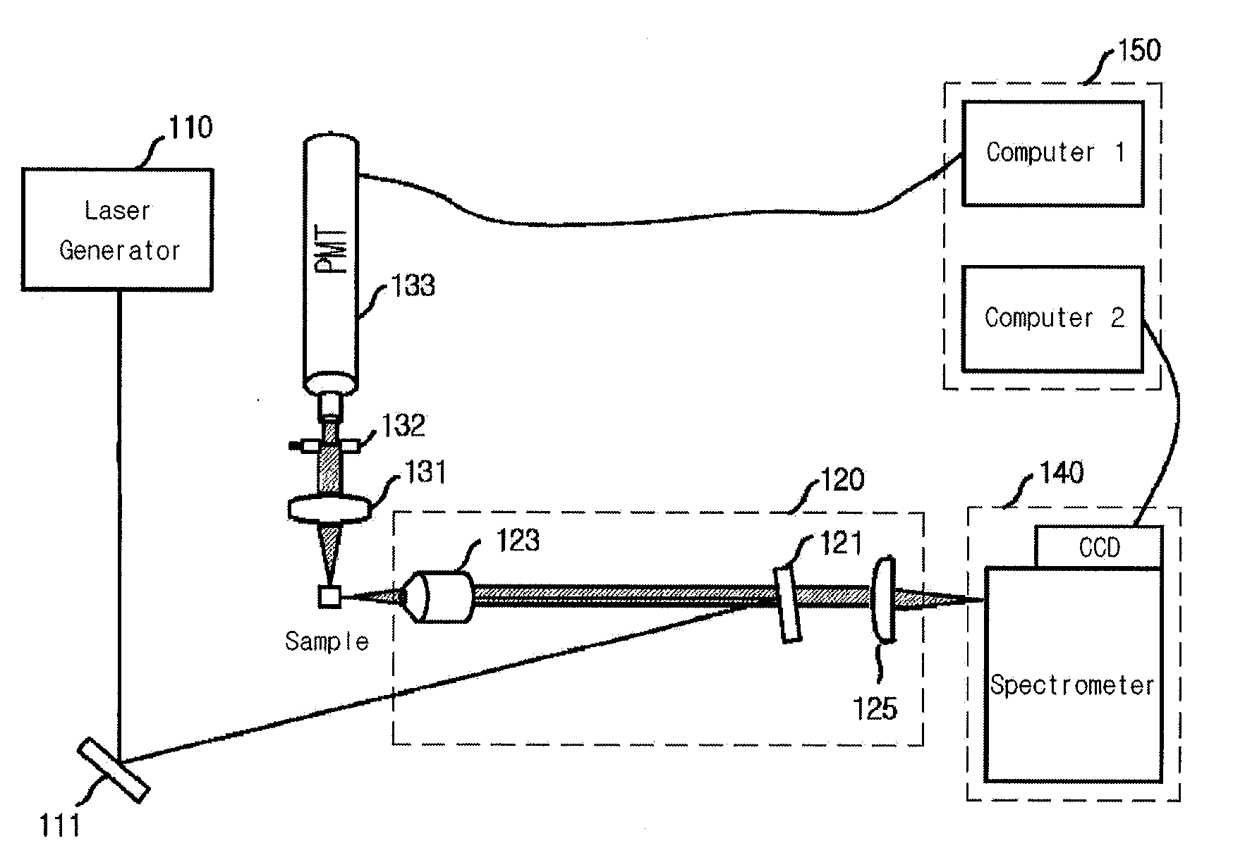
[0019]Using configurational characteristics of the aforementioned light condensing device enables Raman scattering and dynamic light scattering to be simultaneously detected, as proposed in the present invention. First, the 180° geometry light condensing device, which detects Raman scattered light, removes elastic light from the collected scattered light using a notch filter. The light condensing device for detecting light scattering is disposed in a vertical direction with respect to incident light, and can control a light condensing angle to a small degree, if necessary.

[0020]FIG. 1 illustrates a simultaneous detection apparatus of Raman scattering and dynamic light scattering according to Exemplary Embodiment 1 of the present invention.

[0021]Referring to FIG. 1, the simultaneous detection apparatus of Raman scattering and light scattering includes a laser generator 110, a Raman scattering de...

exemplary embodiment 2

Raman Scattering Detection in 90° Geometry and Light Scattering Detection in 90° Geometry

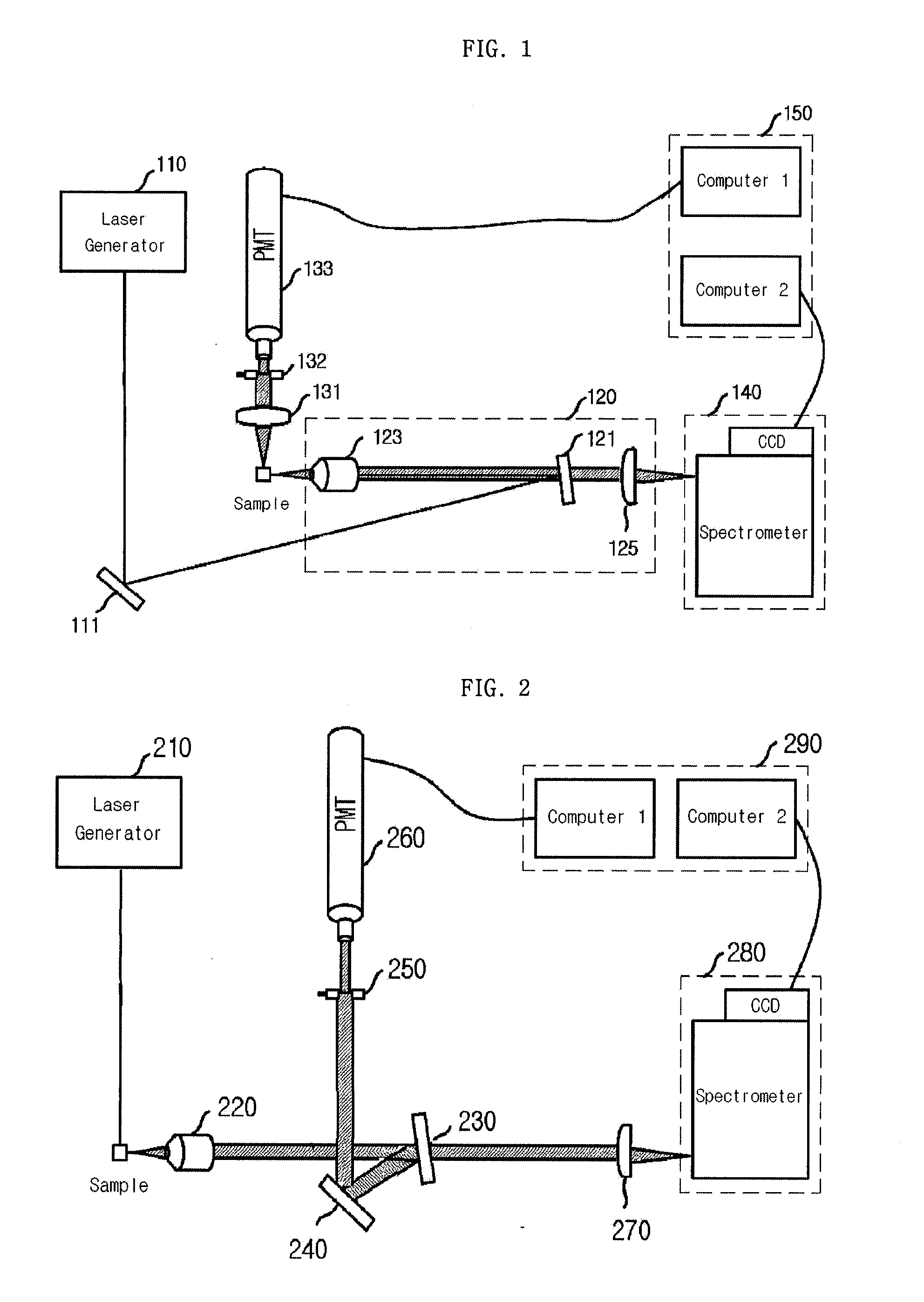
[0026]This is a configuration in which scattered light collected in 90° light collection geometry is separated into Raman scattered light and elastic scattered light by notch and edge filters, thereby simultaneously detecting Raman scattering and light scattering. The 90° light collection geometry is a geometry which is the most commonly used in conventional Raman scattering and dynamic light scattering detection having advantages of the conventional optical configuration as it is. In the light scattering detection, a light condensing angle may be adjusted to small angle through the control of an iris if necessary.

[0027]FIG. 2 illustrates a simultaneous detection apparatus of Raman scattering and dynamic light scattering according to Exemplary Embodiment 2 of the present invention.

[0028]Referring to FIG. 2, it may be noted that the simultaneous detection apparatus of the Raman scattering and lig...

exemplary embodiment 3

Raman Scattering Detection in 180° Geometry and Light Scattering Detection in 180° Geometry

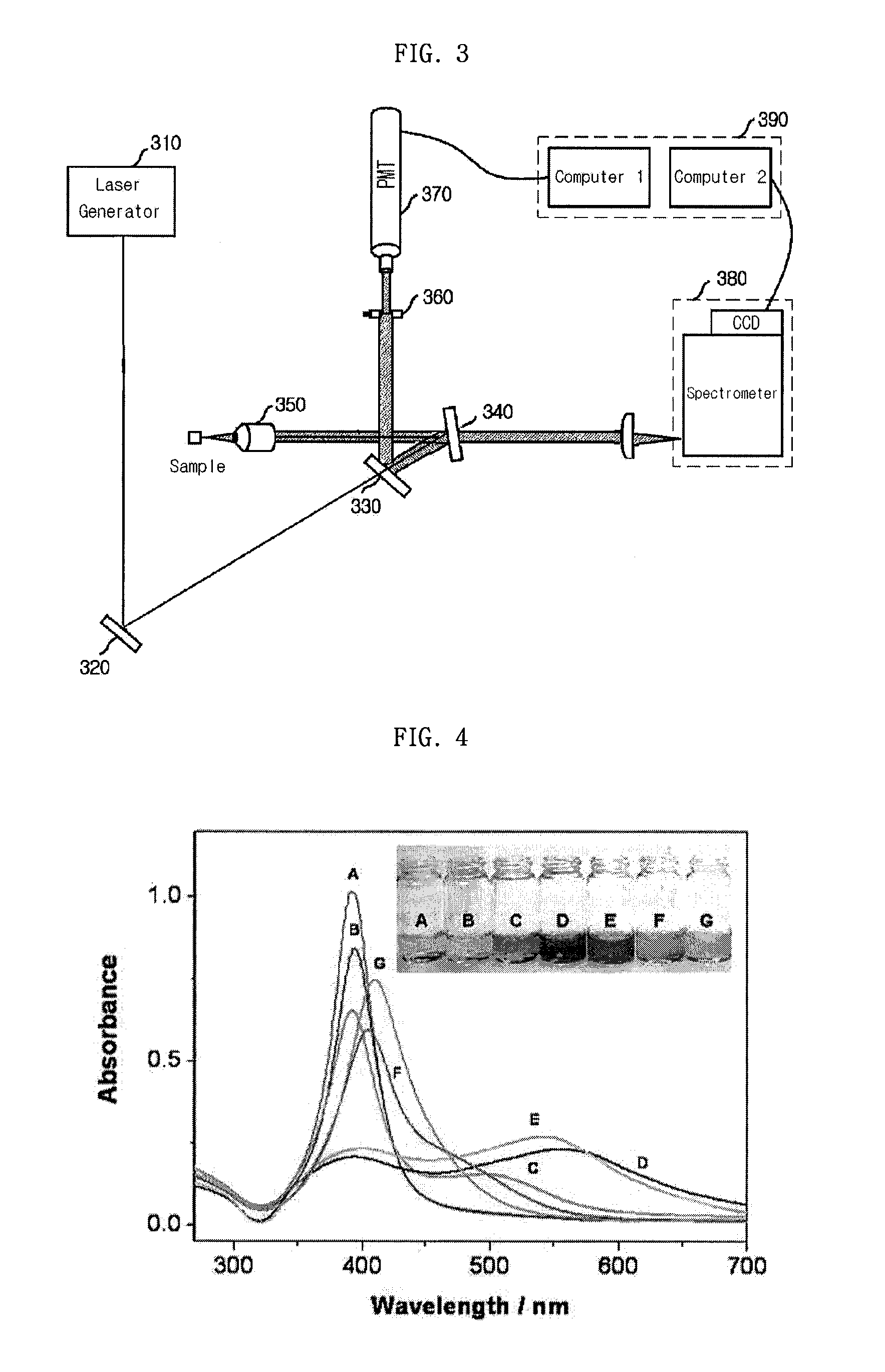
[0030]This is a configuration of separating scattered light condensed in 180° geometry into Raman scattered light and elastic scattered light using a notch filter and simultaneously detecting Raman scattering and light scattering. In order to embody the 180° light condensing geometry, a beam splitter is needed. In light scattering detection, a light condensing angle can be adjusted to small angle through control of an iris if necessary. Since the scattered light in 180° direction has a relatively smaller variation of an autocorrelation function with respect to a light condensing angle, a relatively larger light condensing angle may be used, but scattering intensity in this direction is also relatively small.

[0031]FIG. 3 illustrates a simultaneous detection apparatus of Raman scattering and light scattering according to Exemplary Embodiment 3 of the present invention.

[0032]Referring to FIG. 3, ...


PUM

PropertyMeasurementUnit
angleaaaaaaaaaa
angleaaaaaaaaaa
incident angleaaaaaaaaaa

Abstract

Provided is a detection apparatus of Raman scattering and light scattering, and more particularly, a simultaneous detection apparatus of Raman scattering and dynamic light scattering and a detection method using the same. The simultaneous detection apparatus of Raman scattering and light scattering includes: a detection unit for applying incident light to a sample, and detecting Raman scattering in 90° or 180° geometry and light scattering in 90° or 180° geometry in order to simultaneously collect Raman scattering and light scattering; and a computer connected to the detection unit to obtain at least one of the size and distribution of particles from the detected light scattering, and to obtain information of the molecular structure from the detected Raman scattering. This apparatus may simultaneously observe the size of nano-sized or larger material and molecular information thereof, and phenomena accompanying changes in molecular environment according to material variation and changes of the material in size and distribution, and thus is very useful for studying nano materials and protein antigens and antibodies.

Description

TECHNICAL FIELD[0001]The present invention relates to an apparatus capable of detecting Raman and light scattering, and more particularly, to an apparatus capable of simultaneously detecting Raman and light scattering and a detection method using the same.BACKGROUND ART[0002]Detection apparatuses of Raman and light scattering detect information of a molecule's vibrational structure and particle's size and distribution, respectively. The Raman scattering causes a change in vibration potential of a molecule, and vibration frequency and structural information of the molecule are obtained by measuring the frequency shift of the scattered light from the incident light. Such Raman scattering is inelastic, and scattering energy intensity is approximately 1 / 1000 of that of elastic scattering. Thus, in the Raman scattering, a light collection device needs a device for removing elastic scattered light.[0003]Meanwhile, the light scattering detection apparatus detects size and distribution of n...

Claims


Application Information

Patent Timeline
Patent Type & Authority Applications(United States)
IPC IPC(8): G01N21/65G01N21/47
CPCG01J3/02G01J3/0227G01J3/0291G01N2015/1493G01N2015/0038G01N2015/0092G01J3/44B82Y35/00
Inventor JEONG, DAE-HONGLEE, YOON-SIKCHO, MYUNG-HAINGKIM
Owner SEOUL NAT UNIV R&DB FOUND
Learn More