Vacuum platen for an image forming apparatus

a technology of vacuum platen and image forming apparatus, which is applied in the direction of printing, other printing apparatus, etc., can solve the problem of expensive reprinting of recorded images, and achieve the effect of facilitating a clean cu

Inactive Publication Date: 2010-01-28
EASTMAN KODAK CO
View PDF8 Cites 22 Cited by
  • Summary
  • Abstract
  • Description
  • Claims
  • Application Information

AI Technical Summary

Benefits of technology

[0008]An aspect of the present invention is to provide a media hold-down device as part of an image forming apparatus. By varying the hold-down pressure in response to the extent of coverage of chamber rows by a advancing media to be printed upon, or in response to the extent of coverage of chamber columns by the width of an advancing media, the pressure applied is more appropriate than if it were constant at a level suited to hold down the entire media. In addition, moving t...

Problems solved by technology

It is expensive to reprint a recorded image, which may be neces...

Method used


Image

  • Vacuum platen for an image forming apparatus
  • Vacuum platen for an image forming apparatus
  • Vacuum platen for an image forming apparatus

Examples


Embodiment Construction

[0027]The following groups of terms shall have the same meaning whether used in the specification or claims of the present invention. The terms trough, borderless printing trough and overprint trough shall have the same meaning. The terms hold-down device and vacuum platen shall have the same meaning. The terms airborne ink mist and ink mist shall have the same meaning. The terms negative pressure, partial vacuum and vacuum shall have the same meaning.

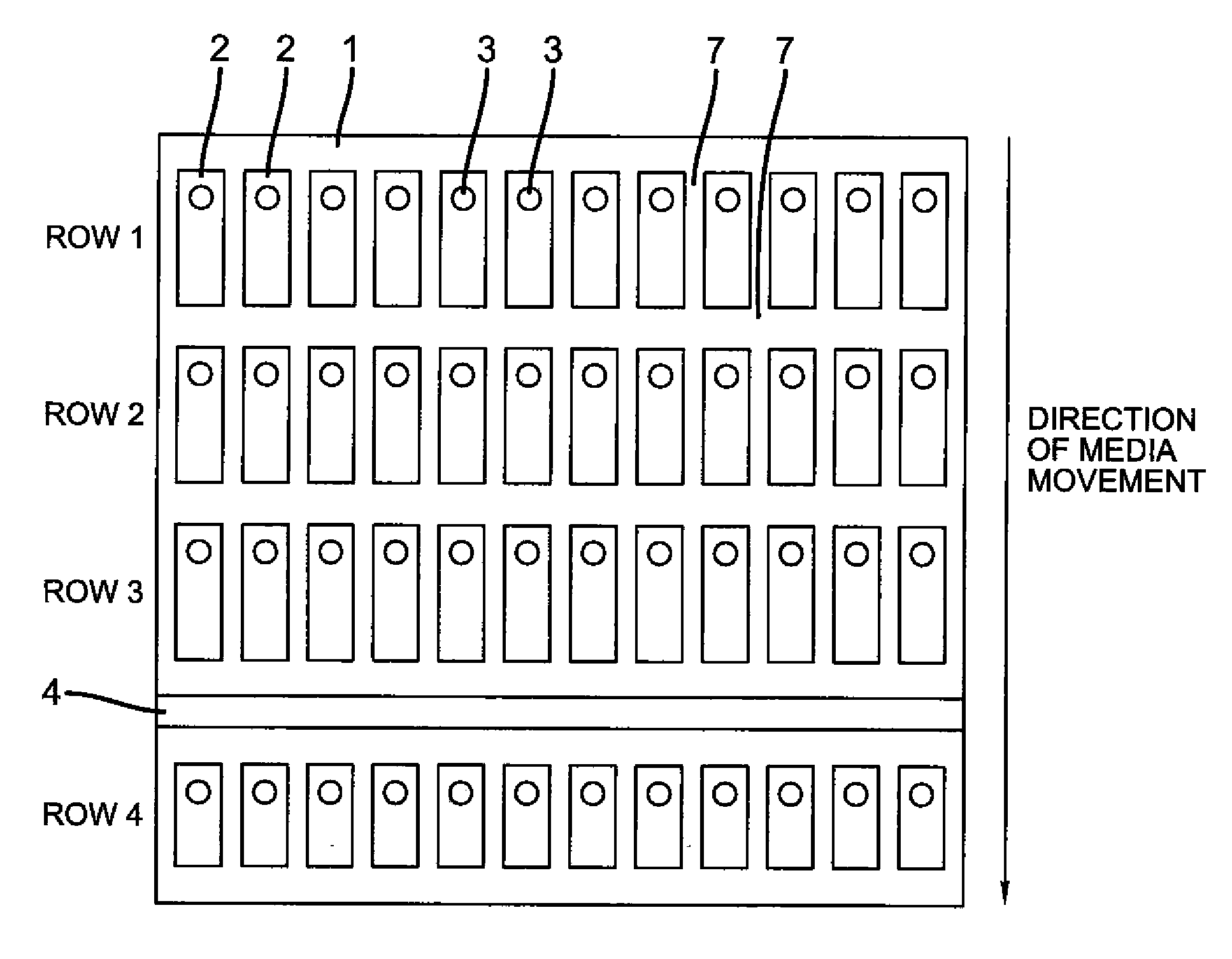
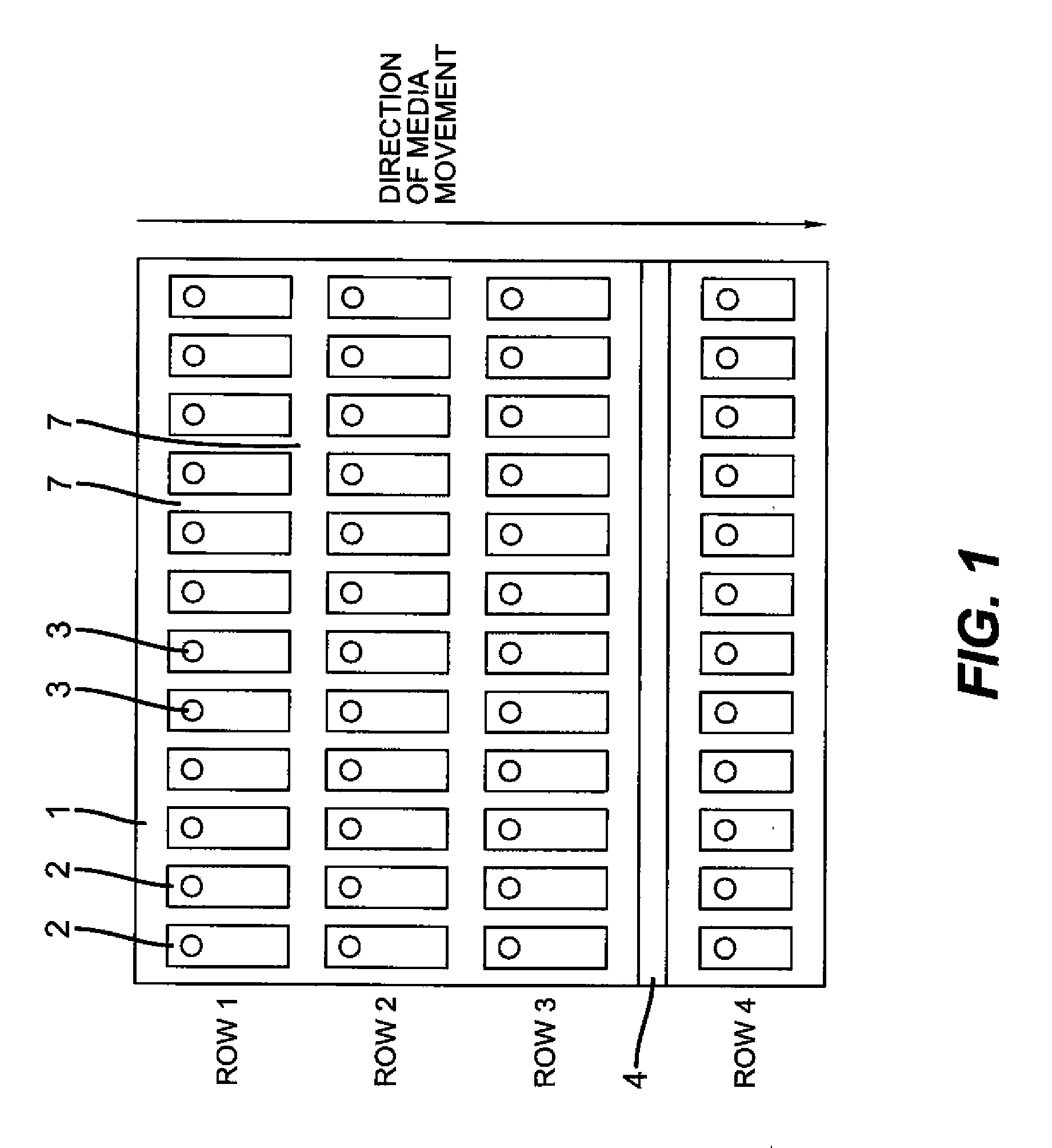
[0028]The first embodiment of the instant invention will be described in terms of FIGS. 1-3, 5, 6 and 8. As illustrated, the vacuum platen 1 includes a matrix or array of vacuum chambers 2 which are in fluid communication with at least one source of negative pressure 100 in FIG. 5 via the ports 3.

[0029]In this embodiment, there are four rows of vacuum chambers 2, such that the distance from one row to the next row is along the media advance direction. However, any number of rows may be used in the present invention. In addition, there ...


PUM


Abstract

An image forming apparatus includes a source of negative pressure; a platen including a plurality of chambers that are connected to the source of negative pressure; and a media sensing system configured to sense an extent of overlay of media over the plurality of chambers of the platen. A controller is responsive to input from the media sensing system. The controller is configured to adjust the source of negative pressure depending on the extent of overlay of media over the plurality of chambers of the platen.

Description

CROSS REFERENCE TO RELATED APPLICATIONS[0001]Reference is made to commonly assigned U.S. patent application Ser. No. ______ (Docket 94524) filed concurrently herewith entitled “OVERPRINT TROUGH FOR AN IMAGE FORMING APPARATUS” in the name of John C. Love and U.S. patent application Ser. No. ______ (Docket 94959) filed concurrently herewith entitled “CUTTING STATION FOR AN IMAGE FORMING APPARATUS” in the name of John C. Love, incorporated herein by reference.FIELD OF THE INVENTION[0002]The present invention relates to a media hold-down device for an image forming apparatus such as printers, plotters, copiers, scanners and facsimile machines. In particular the present invention relates to a suction or vacuum hold-down device to maintain a media flat on a platen or reference surface.BACKGROUND OF THE INVENTION[0003]As one of conventional recording apparatuses, an ink jet recording apparatus is known in which a recording medium is intermittently fed in a recording section. Each time the ...

Claims


Application Information

Patent Timeline
IPC IPC(8): B41J2/01
CPCB41J11/003B41J11/06B41J11/0085
Inventor LOVE, JOHN C.
Owner EASTMAN KODAK CO
Why Eureka
Try Eureka