
Apparatus and method for neural-signal capture to drive neuroprostheses or control bodily function

a neural-signal capture and apparatus technology, applied in the field of optics-based detection of neural activity, can solve the problems of large apparatus, high cost, and not directly suited to clinical monitoring

Inactive Publication Date: 2010-01-21
LOCKHEED MARTIN CORP
View PDF101 Cites 118 Cited by
  • Summary
  • Abstract
  • Description
  • Claims
  • Application Information

AI Technical Summary

Benefits of technology

[0019]In some embodiments, the interaction of the first light signal with the particular nerve or brain area whose activity is being monitored causes a change in scattering, reflection, birefringence or other effect on the light having the first wavelength, and the measuring of the second light signal includes detecting light of the first wavelength. In some embodiments, the first light signal is an emitted light pulse of the first wavelength and the measuring of the second light signal includes detecting light of the first wavelength during one or more time periods shortly following the emitted pulse (e.g., detecting a response waveform (e.g., the amplitude and/or phase delay) of light at the first wavelength) from one or more detection locations. In some embodiments, a mathematical transform is performed on the detected light signal from a plurality of sensors each located at a location (e.g., located at a point of a Cartesian grid or array) that permits triangulation or other location techniques to determine a location in three-dimensional space relative to the patient. For example, in s

Problems solved by technology

Use of the measurement of time gives the method its alternative name, “time-of-flight.” Although the TD method is a valuable tool for conducting basic research, the apparatus is large and expensive and not directly suited to clinical monitoring.

Method used


Image

  • Apparatus and method for neural-signal capture to drive neuroprostheses or control bodily function
  • Apparatus and method for neural-signal capture to drive neuroprostheses or control bodily function
  • Apparatus and method for neural-signal capture to drive neuroprostheses or control bodily function

Examples


Embodiment Construction

[0042]Although the following detailed description contains many specifics for the purpose of illustration, a person of ordinary skill in the art will appreciate that many variations and alterations to the following details are within the scope of the invention. Accordingly, the following preferred embodiments of the invention are set forth without any loss of generality to, and without imposing limitations upon the claimed invention.

[0043]In the following detailed description of the preferred embodiments, reference is made to the accompanying drawings that form a part hereof, and in which are shown by way of illustration specific embodiments in which the invention may be practiced. It is understood that other embodiments may be utilized and structural changes may be made without departing from the scope of the present invention.

[0044]The leading digit(s) of reference numbers appearing in the Figures generally corresponds to the Figure number in which that component is first introduc...


PUM


Abstract

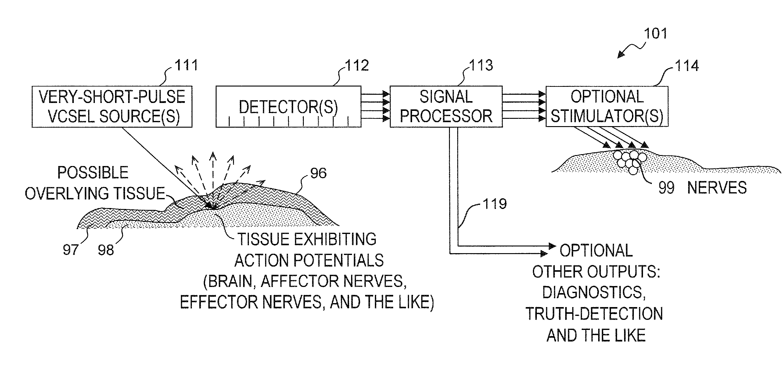
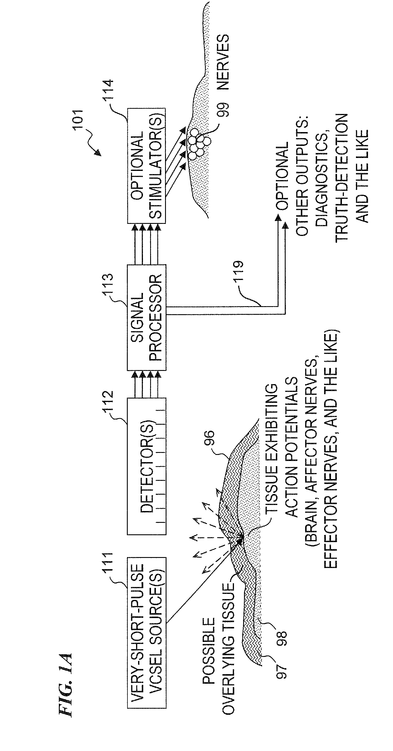
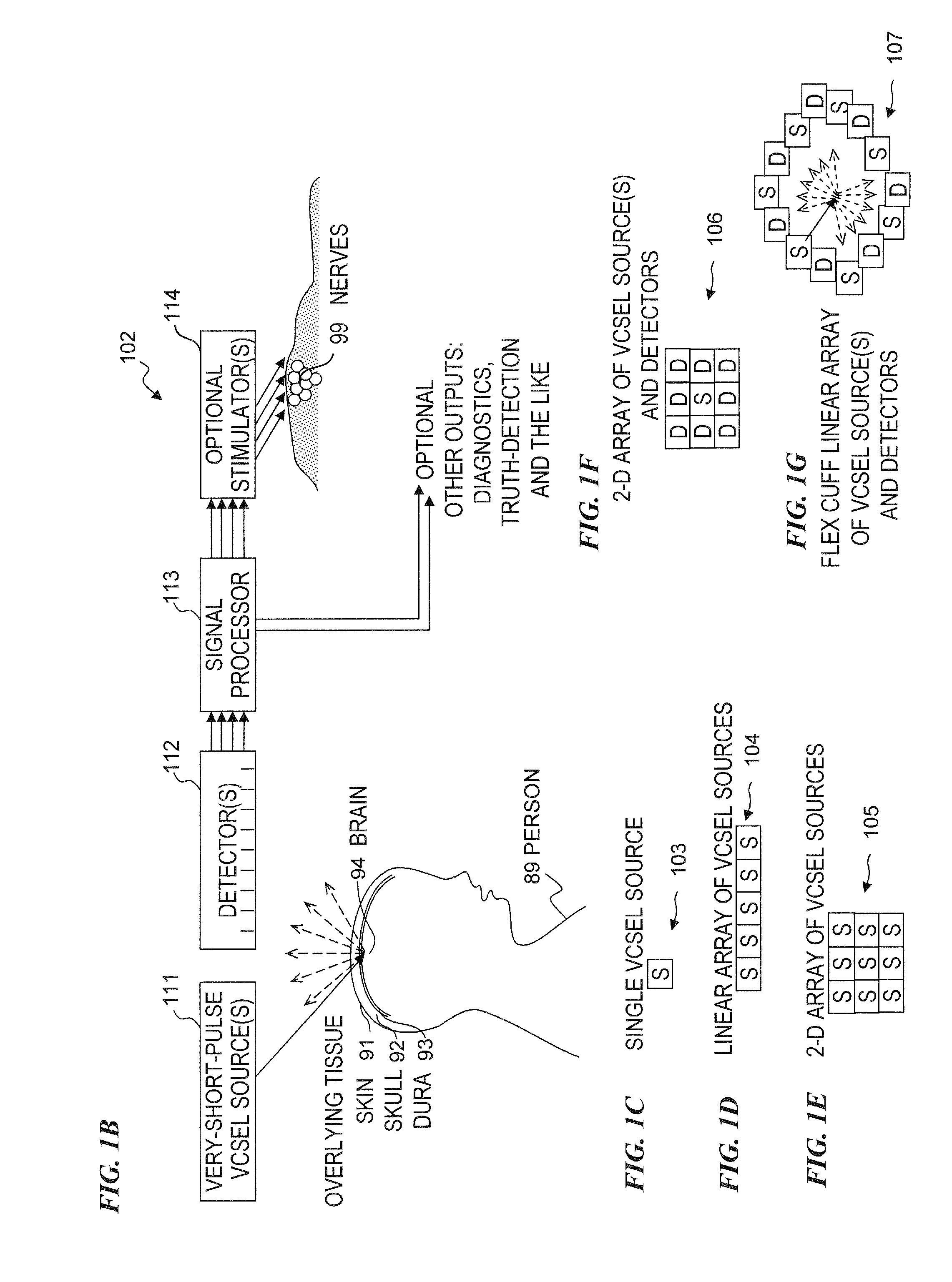
Method and apparatus for detecting nerve activity of an animal. Some embodiments include outputting a light pulse having a wavelength onto a volume of animal tissue such that the light pulse interacts with active nerves of the tissue; measuring a light signal resulting from the interaction of the light pulse with the tissue; transmitting an electrical signal based on the measured light signal; signal-processing the electrical signal; and outputting a response signal, which can optionally be used to control a prosthetic device, stimulate another nerve, or display / diagnose a condition. Some embodiments output a plurality of light wavelengths and / or pulses, which are optionally high-frequency intensity modulated. Some embodiments analyze DC, AC, and phase components of signals to spatially resolve locations of neural activity. Some embodiments output light pulse(s) and detect the resultant light from outside a human skull to detect neural activity of human brain tissue inside the skull.

Description

CROSS-REFERENCE TO RELATED APPLICATIONS[0001]This application claims priority to U.S. Provisional Patent Application 61 / 081,732 (Attorney Docket 5032.044PV1) filed on Jul. 17, 2008, titled “Method and Apparatus for Neural Signal Capture to Drive Neuroprostheses or Bodily Function,” and to U.S. Provisional Patent Application 61 / 226,661 (Attorney Docket 5032.044PV2) filed on Jul. 17, 2009, titled “Method and Apparatus for Neural-Signal Capture to Drive Neuroprostheses or Control Bodily Function,” each of which is incorporated herein by reference in its entirety.[0002]This invention is also related to U.S. patent application Ser. No. 11 / 257,793 filed Oct. 24, 2005 (Attorney Docket No. 5032.009US1) titled “Apparatus and Method for Optical Stimulation of Nerves and Other Animal Tissue,” U.S. patent application Ser. No. 11 / 536,639 filed Sep. 28, 2006 (Attorney Docket No. 5032.020US1) and titled “MINIATURE APPARATUS AND METHOD FOR OPTICAL STIMULATION OF NERVES AND OTHER ANIMAL TISSUE,” U.S...

Claims


Application Information

Patent Timeline
IPC IPC(8): A61B6/00
CPCA61B5/0059A61B5/0075A61B5/0086A61B5/04001G06F3/015A61N1/36003G01N21/359G01N21/64G01N2201/0612A61B5/6868A61B5/4029A61B5/4041A61B5/407A61B5/24
Inventor WELLS, JONATHON D.BENDETT, MARK P.
Owner LOCKHEED MARTIN CORP
Learn More