
High Capacity Battery Cell Employed with Two or More Unit Cells

a battery cell and high capacity technology, applied in the direction of cell components, flat cell grouping, sustainable manufacturing/processing, etc., can solve the problems of low utilizability, complicated and troublesome electrode assembly, and unsuitable jelly roll electrode assembly, so as to improve the structural stability of the secondary battery against external environments such as impacts and vibrations, and the treatment of the unit cell is easy and convenient.

Active Publication Date: 2010-01-21
LG ENERGY SOLUTION LTD
View PDF6 Cites 43 Cited by
  • Summary
  • Abstract
  • Description
  • Claims
  • Application Information

AI Technical Summary

Benefits of technology

[0010]It is an object of the present invention to provide a secondary battery in which the electrical and physical coupling force between cells constituting the secondary battery is increased, whereby the structural stability of the secondary battery is improved.
[0011]It is another object of the present invention to provide a secondary battery in which the capacity of the secondary battery is greatly increased through a simple assembly process.
[0014]Consequently, the secondary battery according to the present invention has advantages in that two or more unit cells are included in one battery case, whereby the capacity of the secondary battery is increased, the unit cells constituting the secondary battery are electrically and mechanically connected to each other via electrode terminals protruding from opposite ends of the unit cells, whereby the structural stability of the secondary battery against external environments, such as impacts and vibrations, is improved. Also, the two or more unit cells are stably coupled to each other as a single unit body, and therefore, the treatment of the unit cells is very easy and convenient during the assembly of the secondary battery.
[0015]In the above-described conventional secondary battery constructed in a structure in which two or more unit cells are connected to each other at only the electrode terminal regions (upper ends) located at one-side ends of the unit cells, and the electrode terminals protrude outward from the battery case, on the other hand, the unit cells are separated from each other at the other-side ends (lower ends) of the unit cells. As a result, the electrode terminal regions at the upper ends of the unit cells may easily break when external impacts or vibrations are applied to the conventional secondary battery. In addition, the treatment of the unit cells is very difficult, during the assembly of the secondary battery, due to the separated lower end structure of the unit cells. The secondary battery according to the present invention solves simultaneously the above-described problems by virtue of the unique structure of the secondary battery.
[0032]According to circumstances, one of the unit cells may include a long separator sheet, and the unit cells are coupled to each other by thermal welding while the remaining end of the separator sheet surrounds all the unit cells. This structure further increases the coupling force between the unit cells, thereby improving the structural stability of the secondary battery.

Problems solved by technology

The jelly-roll type electrode assembly is suitable for cylindrical batteries; however, the jelly-roll type electrode assembly is not suitable for prismatic batteries or pouch-shaped batteries because the electrode active material may be detached, and the spatial utilizability is low.
The stacking type electrode assembly has an advantage in that the stacking type electrode assembly can be constructed in a prismatic structure; however, the stacking type electrode assembly has disadvantages in that a process for manufacturing the stacking type electrode assembly is complicated and troublesome, and, when external impacts are applied to the stacking type electrode assembly, electrodes of the stacking type electrode assembly are pushed with the result that short circuits occur in the stacking type electrode assembly.
As the number of the full cells or bicells is increased, however, a great deal of working time is required to fold the increased full cells or bicells.
In addition, when some of the cells malfunction, the electrode assembly also malfunctions.
However, these technologies have problems in that the two or more electrode assemblies are coupled to each other only at electrode terminals thereof in order to accomplish the electrical connection between the electrode assemblies, and the electrode terminals protrude from only one-side ends of the electrode assemblies, whereby the structural stability of the secondary battery is very low.
This problem may act as one of the major factors to deteriorate the stability of the secondary battery when the secondary battery is exposed to external environments, such as impacts and vibrations, which are frequently generated in the secondary battery requiring high capacity.

Method used


Image

  • High Capacity Battery Cell Employed with Two or More Unit Cells
  • High Capacity Battery Cell Employed with Two or More Unit Cells
  • High Capacity Battery Cell Employed with Two or More Unit Cells

Examples


Embodiment Construction

[0045]Now, preferred embodiments of the present invention will be described in detail with reference to the accompanying drawings. It should be noted, however, that the scope of the present invention is not limited by the illustrated embodiments.

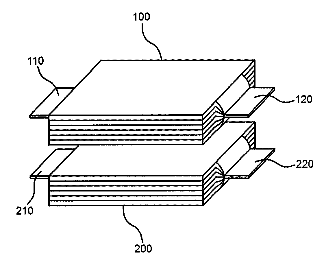
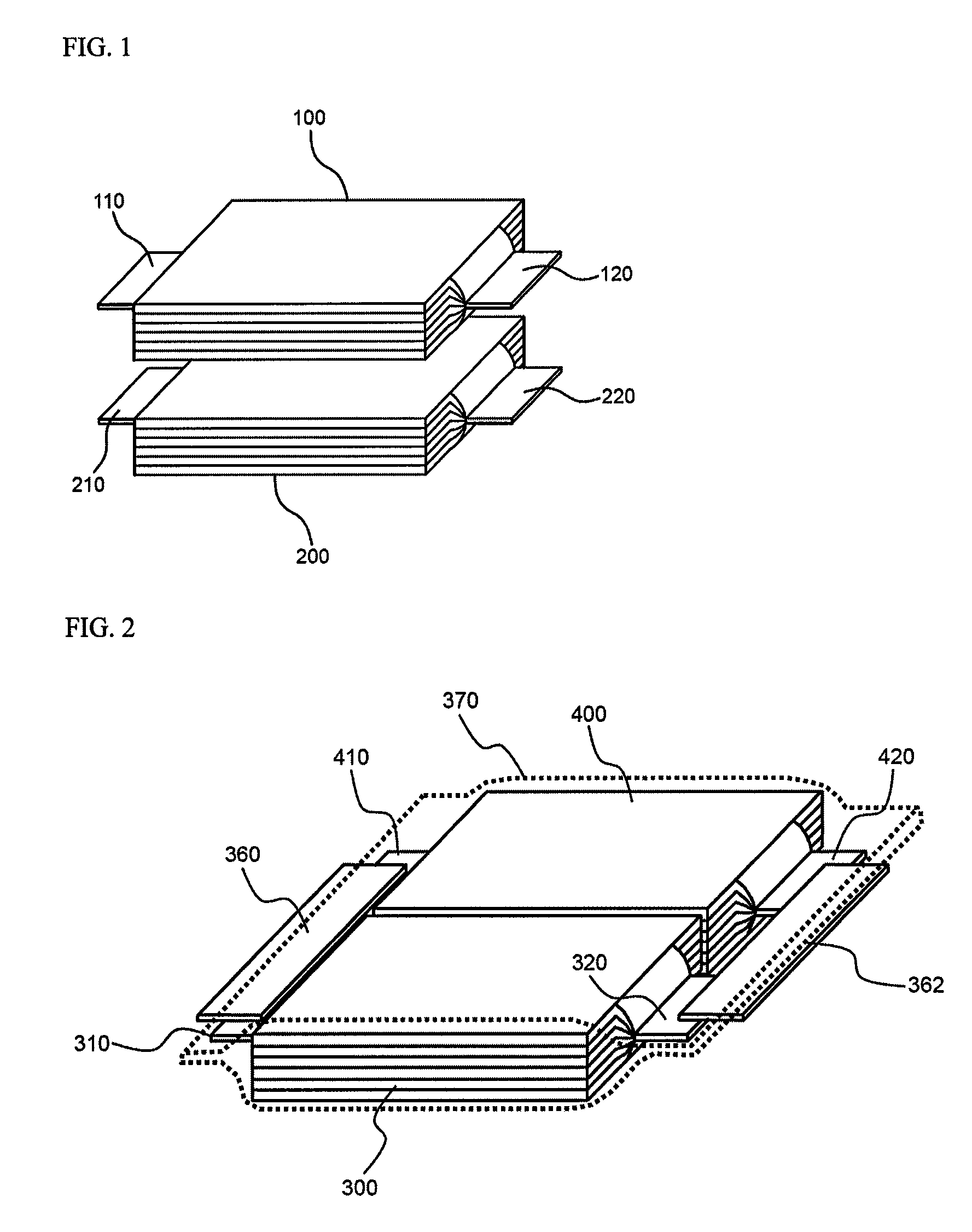
[0046]FIG. 1 is a perspective view typically illustrating a stacking arrangement type parallel connection structure of unit cells constituting a secondary battery according to a preferred embodiment of the present invention.

[0047]Referring to FIG. 1, unit cells (a first unit cell and a second unit cell) 100 and 200 are constructed in a structure in which a plurality of bicells having a stacking structure having identical electrodes at opposite sides thereof are folded while a separator sheet is disposed between the bicells. The structure of the bicells is illustrated in more detail in FIG. 4.

[0048]Referring to FIG. 4, the first unit cell 100 is constructed in a structure in which bicells 150 and 152 having a cathode / separator / anode / separator...


PUM


Abstract

Disclosed herein is a secondary battery including two or more stacking-folding type cells (‘unit cells’) manufactured by winding small-sized electrode assemblies (‘bicells’) constructed in a stacking type structure in which electrodes having the same polarity are located at opposite sides of each electrode assembly and small-sized electrode assemblies (‘full cells’) constructed in a stacking type structure in which electrodes having different polarities are located at opposite sides of each electrode assembly using a long separator sheet, wherein the unit cells are mounted in a battery case, each unit cell has one or more electrode terminals protruding from each end of each unit cell, and the unit cells are mounted in a receiving part of the battery case such that the unit cells are arranged in a stacking arrangement structure or a plane arrangement structure while the electrode terminals of the unit cells are connected with each other. According to the present invention, the electrical and physical coupling force between the unit cells is increased. Consequently, the high-capacity secondary battery according to the present invention exhibits an improved structural stability. In addition, it is possible to greatly increase the capacity of the secondary battery according to the present invention through a simple assembly process.

Description

FIELD OF THE INVENTION[0001]The present invention relates to a high-capacity battery cell including two or more unit cells, and, more particularly, to a secondary battery including two or more stacking-folding type cells (‘unit cells’) manufactured by winding small-sized electrode assemblies (‘bicells’) constructed in a stacking type structure in which electrodes having the same polarity are located at opposite sides of each electrode assembly and small-sized electrode assemblies (‘full cells’) constructed in a stacking type structure in which electrodes having different polarities are located at opposite sides of each electrode assembly using a long separator sheet, wherein the unit cells are mounted in a battery case, each unit cell has one or more electrode terminals protruding from each end of each unit cell, and the unit cells are mounted in a receiving part of the battery case such that the unit cells are arranged in a stacking arrangement structure or a plane arrangement stru...

Claims


Application Information

Patent Timeline
IPC IPC(8): H01M6/10H01M10/05H01M10/0583H01M10/0585H01M50/528H01M50/529
CPCH01M2/202H01M2/24H01M2/1072H01M2/1016H01M2/1022H01M6/42H01M50/529Y02P70/50H01M50/20H01M10/052
Inventor YOO, KWANGHORYU, JI HEONPARK, HYUNWOO
Owner LG ENERGY SOLUTION LTD
Learn More