Mutistable Reflective Liquid Crystal Device

Inactive Publication Date: 2010-01-21
SYBRE
View PDF7 Cites 16 Cited by
  • Summary
  • Abstract
  • Description
  • Claims
  • Application Information

AI Technical Summary

Benefits of technology

[0015]In contrast to some prior art arrangements, rather than trying to remove defects, the present invention takes advantage of these and uses them to provide multistable states. Indeed, the walls of the containment structures are used to induce the formation of defect structures. By applying an appropriate electric field, the distortion region(s) can be switched between these states. This can be done substantially in-plane, thereby avoiding or at least reducing the loss of contrast at oblique viewing.
[0016]The confine

Problems solved by technology

However, they have a high-energy demand due to the need for constant power to be applied to hold a pixel in one state.
Furthermore, transmissive displays typically require backlighting from a light source to achieve a bright picture with high contrast, which in turn further increases the power consumption, leading to a shortened battery life.
In addition, since these systems employ out of plane switching, where the LC molecules align themselves perpendicularly to the plane of the substrates in the presence of the electric field, birefringence effects can lead to a loss of contrast when viewed from the side.
The

Method used


Image

  • Mutistable Reflective Liquid Crystal Device
  • Mutistable Reflective Liquid Crystal Device
  • Mutistable Reflective Liquid Crystal Device

Examples


Example

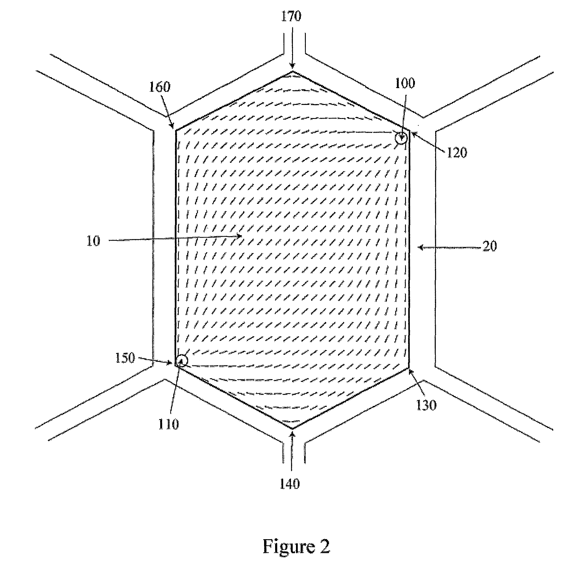
[0039]Containing liquid crystals within containment structures having certain shapes and dimensions can lead to the tendency of the liquid crystal molecules to arrange themselves into one of a multiple of stable states, each stable state having differing director structures and possibly different locations of regions of high distortion. A high distortion location is a region where the liquid crystal molecular order is significantly reduced compared to the bulk and a large elastic distortion occurs, as discussed by Repnik et al. in European Journal of Physics, Vol. 24, pages 481-492 (2003).

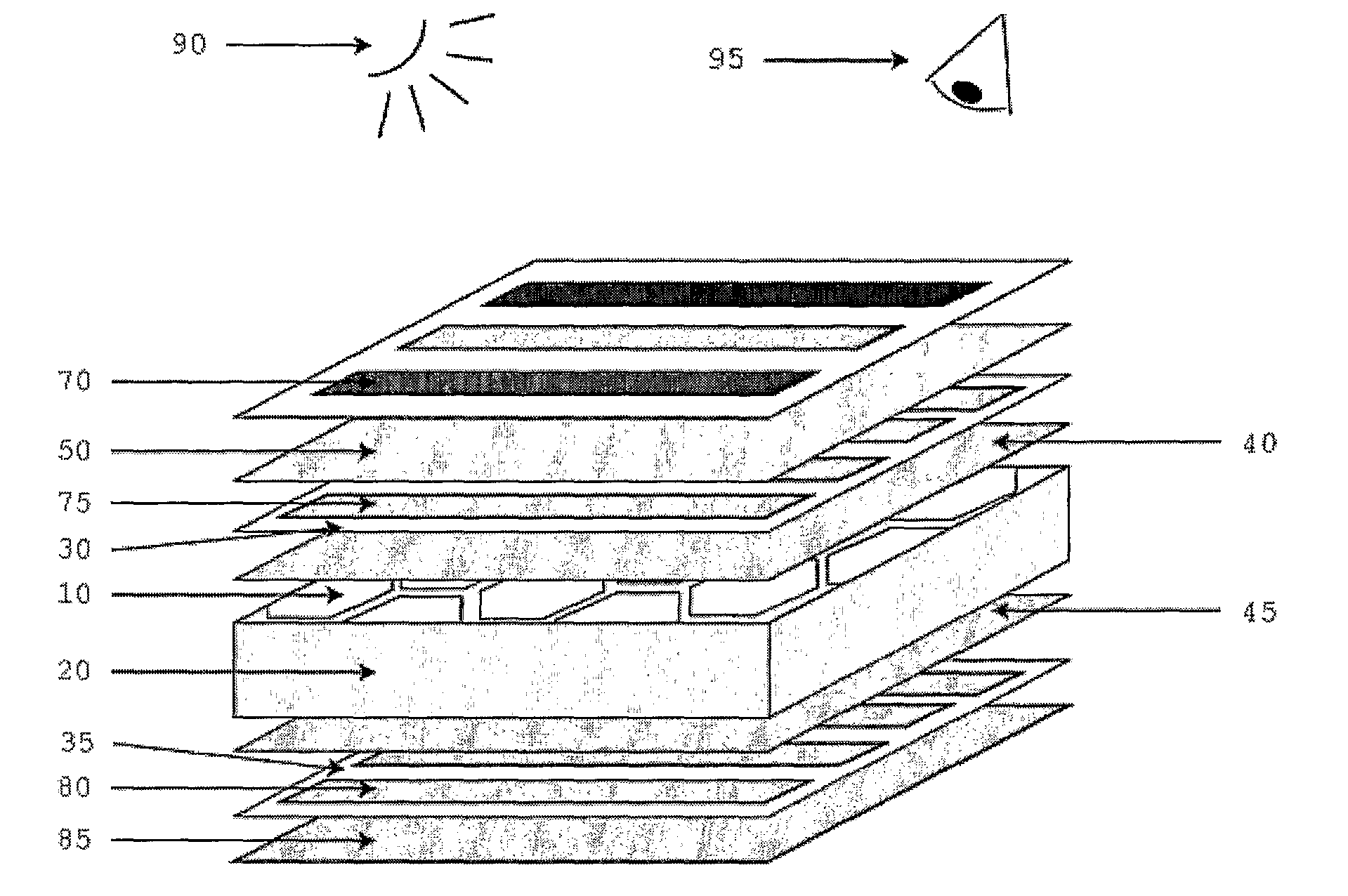
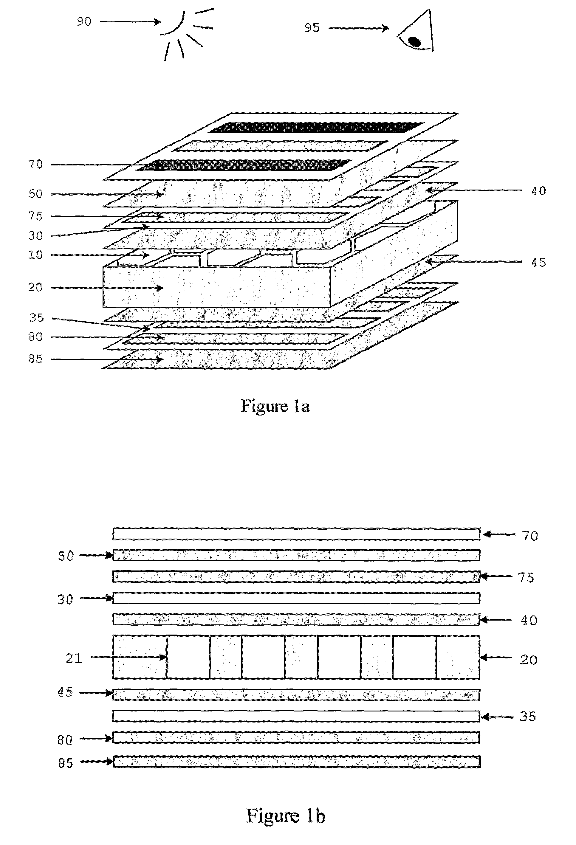
[0040]FIGS. 1(a) and (b) shows a reflective liquid crystal device having a liquid crystal material 10 contained within a containment structure 20 that defines a plurality of openings 21. The containment structure 20 is sandwiched between two transparent substrates 30, 35, which may have alignment layer preparations 40, 45 adhered to faces in contact with the liquid crystal material 10. The containm...


PUM


Abstract

A multistable liquid crystal device having liquid crystal molecules in one or more cavities, wherein at least one liquid crystal region of high distortion (100, 110) is formed in each cavity, the distortion region (100, 110) being switchable between at least two stable states on application of an electric field, the device being such that at least one of the stable states may be utilised as a reflective mode.

Description

[0001]The present invention relates to a multistable reflective liquid crystal device and a liquid crystal display that includes such a device.BACKGROUND[0002]Liquid crystal materials (LCs) consist of rod-like molecules that prefer to align parallel to each other and are capable of being aligned by applied electric fields. The long-range order caused by the local alignment of molecules enables the “director”, the average molecular direction, to be defined. The long and short axes of these molecules exhibit different optical properties and certain molecular orientations can therefore alter the polarisation and intensity of incident light. These reorientation and polarisation effects can be utilised in conjunction with optical elements such as polarising and reflective layers to produce optical devices such as optical switches, changeable phase gratings or displays.[0003]Existing LC devices commonly have two transparent substrates, with semi-transparent electrodes that may be patterne...

Claims


Application Information

Patent Timeline
IPC IPC(8): G02F1/133G02F1/13
CPCG02F1/133377G02F1/133553G02F1/1337G02F1/1391G02F1/133753G02F1/134363G02F1/133707G02F1/1333G02F1/1335G02F1/1343G02F1/139
Inventor MOTTRAM, NIGELDAVIDSON, ANDREW
Owner SYBRE
Why Eureka
Try Eureka