
Locking system for shipping container including bolt seal and electronic device with arms for receiving bolt seal

a technology of electronic device and seal, which is applied in the field of shipping containers, can solve the problems of theft or loss assignment, inability to readily locate the means for determining when or where bolts were cut and replaced, and difficulty in best case theft or loss assignmen

Active Publication Date: 2010-01-21
GOOGLE LLC
View PDF99 Cites 94 Cited by
  • Summary
  • Abstract
  • Description
  • Claims
  • Application Information

AI Technical Summary

Benefits of technology

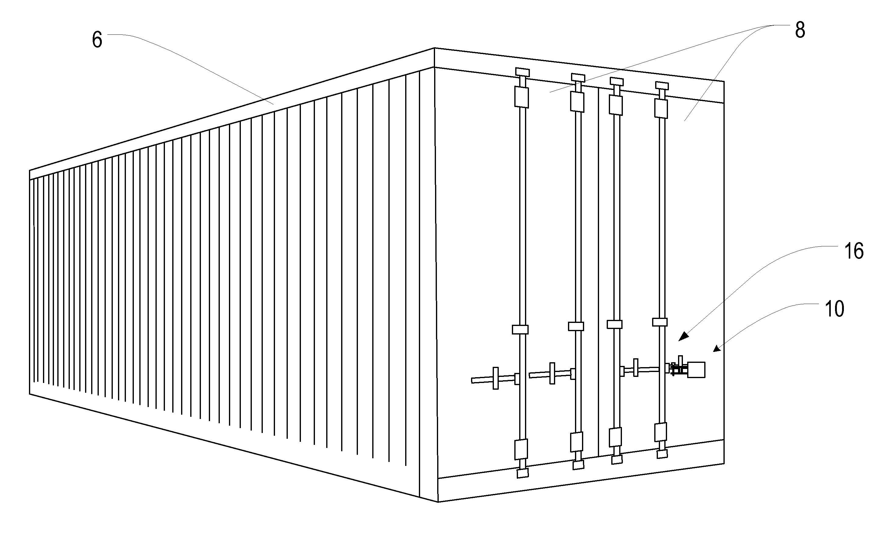
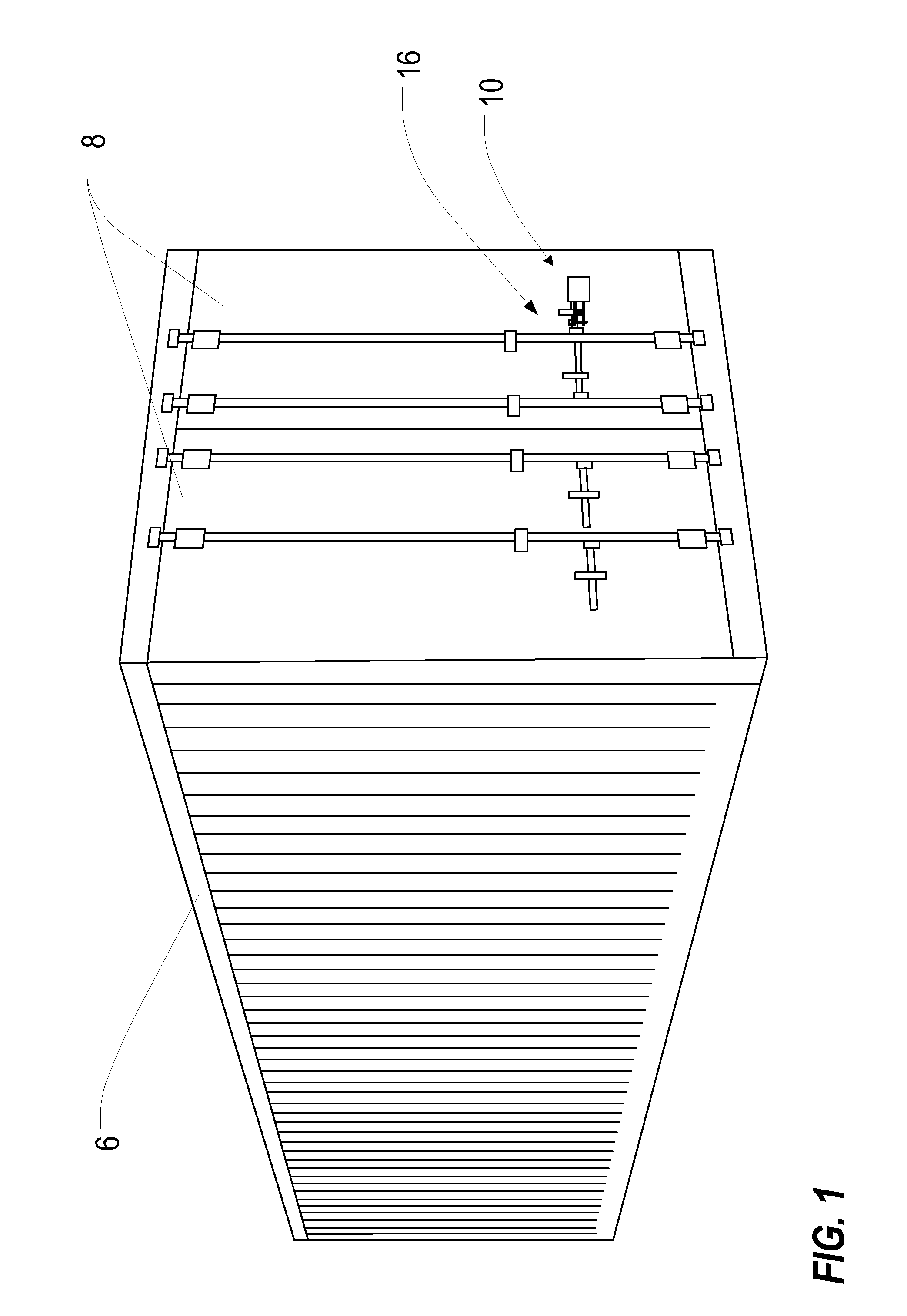
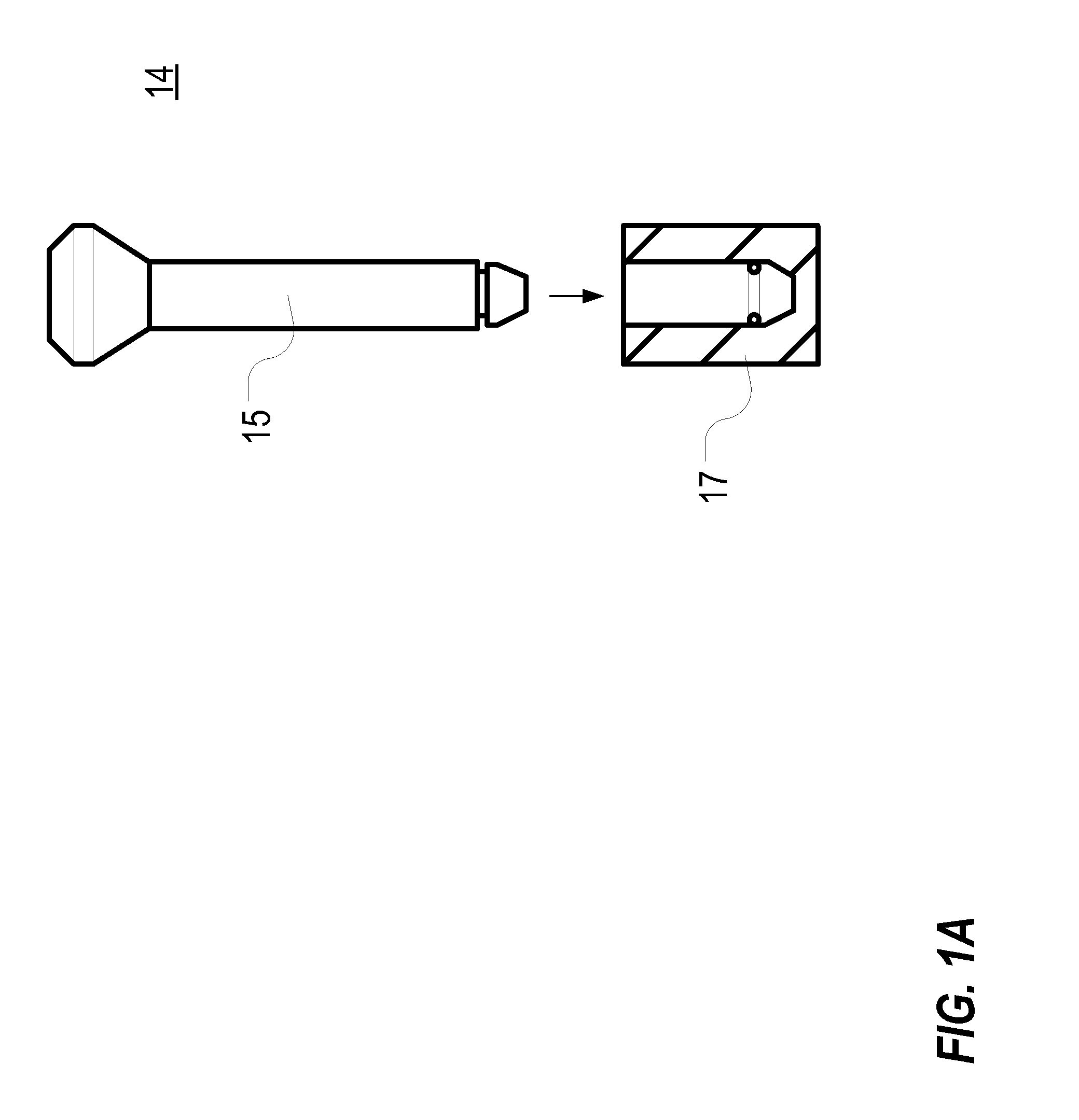
[0011]In a feature of this aspect of the invention, the housing further includes a support carriage and a barrier to prevent access to the electronics enclosure from the support carriage. In another feature, the electronics record the state of the sensing circuit. In a further feature, the electronics record the state of the sensing circuit in computer-readable medium that is contained in the electronics compartment. In still another feature, the electronics report the state of the sensing circuit. In a further feature still, the electronics report the state of the sensing circuit through wireless communications. In an additional feature, the housing comprises a rugged mechanical housing. In yet another feature, the arms are configured to concurrently receive a bolt therethrough when in the locked configuration. In another feature, a bolt of a bolt seal extends through a respective opening in each of the

Problems solved by technology

Although there is an ISO standard for these bolts, they are not necessarily identical from one manufacturer to another.
Although far from fool proof, the technique does provide a simple method of keeping the doors on shipping containers closed unless deliberate action is taken to cut the bolt.
Unfortunately, there is no means readily available for determining when or where bolts were cut and replaced.
Theft or loss assignment, therefore, can be difficult at best.

Method used


Image

  • Locking system for shipping container including bolt seal and electronic device with arms for receiving bolt seal
  • Locking system for shipping container including bolt seal and electronic device with arms for receiving bolt seal
  • Locking system for shipping container including bolt seal and electronic device with arms for receiving bolt seal

Examples


Embodiment Construction

[0047]As a preliminary matter, it will readily be understood by one having ordinary skill in the relevant art (“Ordinary Artisan”) that the present invention has broad utility and application. Furthermore, any embodiment discussed and identified as being “preferred” is considered to be part of a best mode contemplated for carrying out the present invention. Other embodiments also may be discussed for additional illustrative purposes in providing a full and enabling disclosure of the present invention. Moreover, many embodiments, such as adaptations, variations, modifications, and equivalent arrangements, will be implicitly disclosed by the embodiments described herein and fall within the scope of the present invention.

[0048]Accordingly, while the present invention is described herein detail in relation to one or more embodiments, it is to be understood that this disclosure is illustrative and exemplary of the present invention, and is made merely for the purposes of providing a full...


PUM


Abstract

An electronic locking device secures a shipping container and includes a housing, two arms, a sensing circuit, and electronics. The pair of arms extend from the housing and couple to the hasp. The arms transition between locked and unlocked configurations relative to the hasp, with one or both of the arms pivoting relative to the other. A bolt seal locks the arms in the locked configuration. The sensing circuit, which includes sensing contacts, is in a “closed” state or “open” state depending on whether the arms are in the locked or unlocked configuration. The electronics record and report the state of the sensing circuit, thereby indicating whether the arms are locked or unlocked.

Description

CROSS-REFERENCE TO RELATED APPLICATION[0001]The present application is a continuation-in-part of, and claims priority under 35 U.S.C. §120 to, each of: international patent applications PCT / US09 / 44276 and PCT / US09 / 44277, both filed May 16, 2009. The present application also is a nonprovisional of, and claims priority under 35 U.S.C. §119(e) to, each of: U.S. provisional patent application 61 / 053,665, filed May 16, 2008; U.S. provisional patent application 61 / 109,494, filed Oct. 29, 2008; and U.S. provisional patent application 61 / 151,168, filed Feb. 9, 2009. The present application further is a nonprovisional application of, and claims priority under §119(e) to, each of U.S. provisional patent application Nos. 61 / 140,882; 61 / 140,887; 61 / 140,888; 61 / 141,021; 61 / 147,917; and 61 / 155,887. Each of these international applications and provisional applications from which priority is claimed, and the disclosures thereof, are incorporated herein by reference. Additionally, the present applic...

Claims


Application Information

Patent Timeline
IPC IPC(8): E05B45/06E05B65/06
CPCG08B13/08G08B13/126G09F3/0376G09F3/0329G09F3/0317Y10T70/5212Y10T70/5199
Inventor BERGER, THOMAS R.DENNY, JOSEPH E.
Owner GOOGLE LLC
Learn More