
Assembly of a spindle and guide therefor

a spindle and guide technology, applied in the field of parasols, can solve the problems of requiring a relatively large amount of energy and exacerbated problems, and achieve the effect of simple and inexpensive making and simple us

Inactive Publication Date: 2010-01-21
ZHEJIANG ZHENGTE CO LTD
View PDF11 Cites 21 Cited by
  • Summary
  • Abstract
  • Description
  • Claims
  • Application Information

AI Technical Summary

Benefits of technology

[0004]A further object of the invention is to provide a parasol which comprises an actuator assembly and is simple and inexpensive to make.
[0005]A further object of the invention is to provide an actuator assembly of this type which is simple to use for, for example, parasols.
[0009]This parasol has a stable actuator which is simple to make from inexpensive, readily available components. In addition, it is simple to provide the actuator with a drive, such as an electric motor. Furthermore, as a result of the low resistance of the actuator, all that is required is therefore a relatively light electric motor which, if appropriate, can be driven even by means of photovoltaically generated electricity.
[0017]Providing the guide with the specific arrangement of bodies of revolution can provide a spindle which comprises a guide and can be activated in a simple manner and without large losses of friction and is also very stable. In particular, the choice of the positions of the bodies of revolution produces substantial sturdiness, although it has also been found to be possible to make the guide from simple and relatively inexpensive components.
[0028]In an embodiment, the drive unit is coupled to an end of the spindle for causing the spindle to rotate about its longitudinal axis.

Problems solved by technology

However, the design of the spindle and spindle nut has relatively high resistance, as a result of which opening and closing requires a relatively large amount of energy.
If the selected design is used for a parasol, and in particular for large parasols which are nowadays popular, that problem will be exacerbated still further.

Method used


Image

  • Assembly of a spindle and guide therefor
  • Assembly of a spindle and guide therefor
  • Assembly of a spindle and guide therefor

Examples


Embodiment Construction

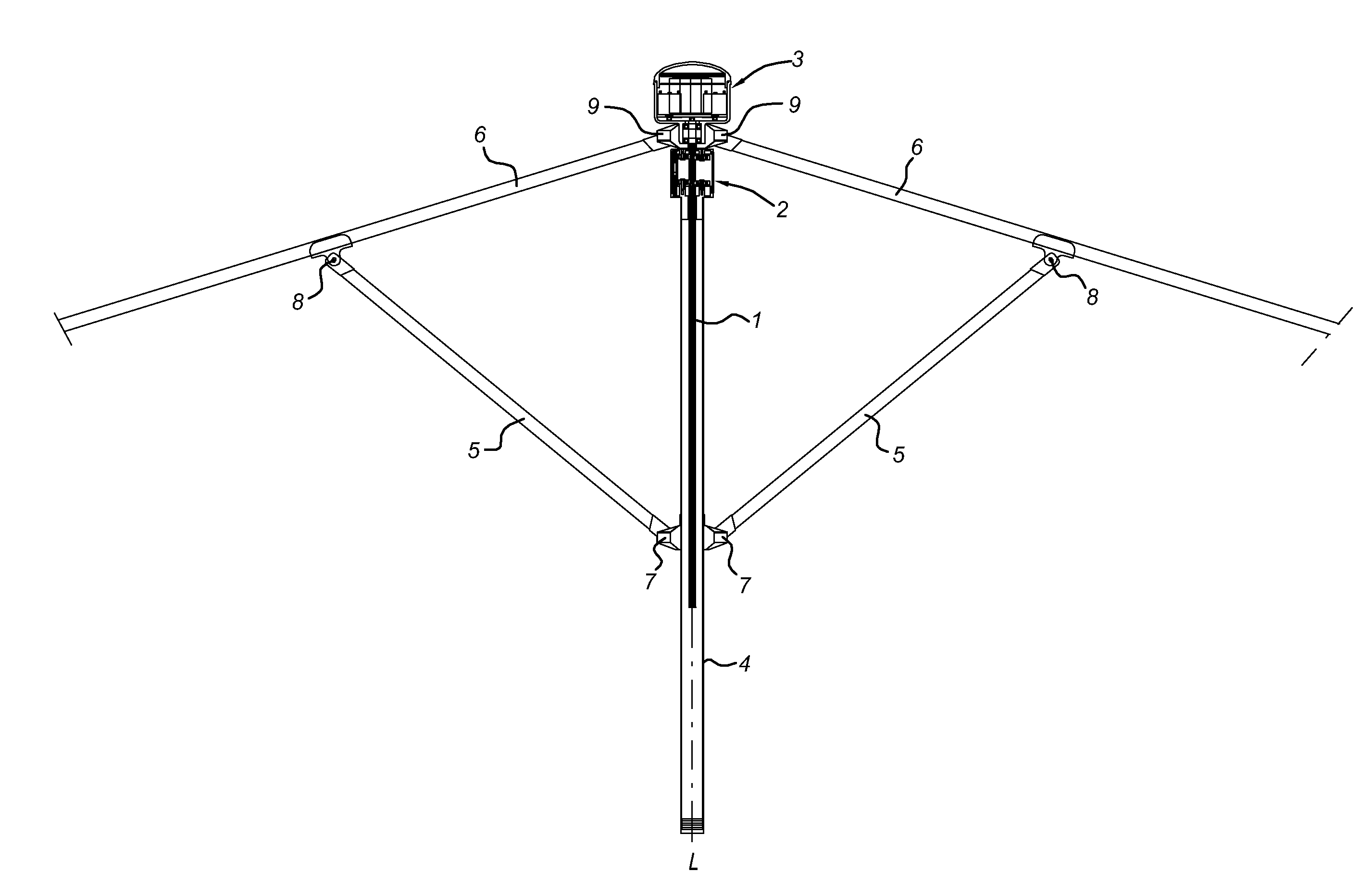
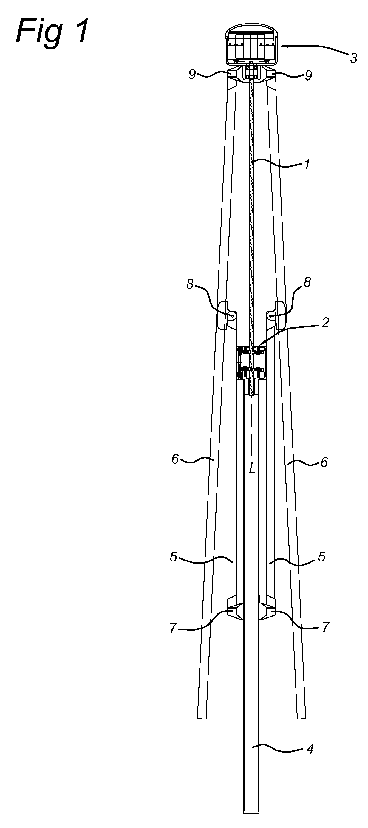
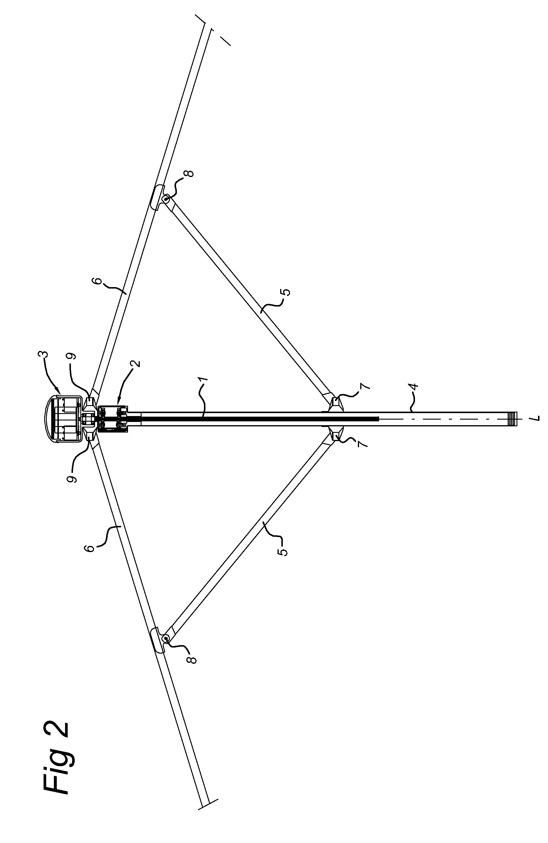
[0058]FIG. 1 shows a parasol in the collapsed state comprising an assembly provided with a spindle 1 which has an external screw thread and is provided at one end with a housing 3 which is positioned rotatably thereon and provided with drive means for causing the spindle 1 to rotate about its longitudinal axis. At its other end, the spindle 1 is in this case provided with a guide 2. In this embodiment of an assembly according to the invention, the guide is used for the collapsing and extending of a parasol. For this purpose, the guide 2 is positioned on a stem 4. The stem 4 is in this case provided with a hinge which is secured thereto and has operating arms 5 which are fastened hingeably thereto and are fastened in turn, at their opposite end, to stays 6 by means of hinges 8. The stays 6 are in turn hingeably fastened to hinges 9 which are connected to the housing 3 containing, as stated hereinbefore, also the operating and drive mechanism for the spindle. As may be seen, in FIG. 1...


PUM


Abstract

The invention relates to a parasol provided with an actuator assembly comprising a spindle having a spindle longitudinal axis and an external screw thread, and a guide for the spindle comprising a holder which extends along a portion of the spindle and which is provided with at least a first and second set of bodies of revolution which are held in the holder body so as to be able to rotate about their axis of rotation and enter into contact with the spindle, where they engage with at least one screw thread part, the second set of bodies of revolution being set apart from the first set of bodies of revolution along the spindle longitudinal axis.

Description

BACKGROUND TO THE INVENTION[0001]The invention relates to a parasol comprising stays which are hingeable at one end and operating arms which are hingeably coupled at one end to the stays.[0002]JP-A-08 103314 describes an umbrella provided with a spindle and spindle nut. However, the design of the spindle and spindle nut has relatively high resistance, as a result of which opening and closing requires a relatively large amount of energy. If the selected design is used for a parasol, and in particular for large parasols which are nowadays popular, that problem will be exacerbated still further.SUMMARY OF THE INVENTION[0003]An object of the invention is to solve at least some of the problems outlined.[0004]A further object of the invention is to provide a parasol which comprises an actuator assembly and is simple and inexpensive to make.[0005]A further object of the invention is to provide an actuator assembly of this type which is simple to use for, for example, parasols.[0006]An addi...

Claims


Application Information

Patent Timeline
Patent Type & Authority Applications(United States)
IPC IPC(8): A45B25/14F16H25/22
CPCA45B25/14F16H25/2266A45B2200/1027
Inventor STOELINGA, DIRK JAN
Owner ZHEJIANG ZHENGTE CO LTD
Learn More