
Mechanical roller tappet for an internal combustion engine

Inactive Publication Date: 2010-01-21
SCHAEFFLER TECH AG & CO KG
View PDF1 Cites 16 Cited by
  • Summary
  • Abstract
  • Description
  • Claims
  • Application Information

AI Technical Summary

Benefits of technology

[0003]The object of the present invention is therefore to improve a roller tappet of the pre-cited type, so that the aforesaid drawbacks are eliminated by simple measures. The roller tappet should not only have a high light-weight and cos

Problems solved by technology

Although this one-piece, shaped sheet metal tappet housing has a high light-weight and cost-saving potential, the structure of such a roller tappet has considerable inherent drawbacks.
On the other hand, the introduction of supporting forces of the axle mounting the drive roller into the axle eyes, which are arranged directly in the tappet skirt, is to be seen as a critical factor in so far a

Method used


Image

  • Mechanical roller tappet for an internal combustion engine
  • Mechanical roller tappet for an internal combustion engine
  • Mechanical roller tappet for an internal combustion engine

Examples


Example

DETAILED DESCRIPTION OF THE DRAWINGS

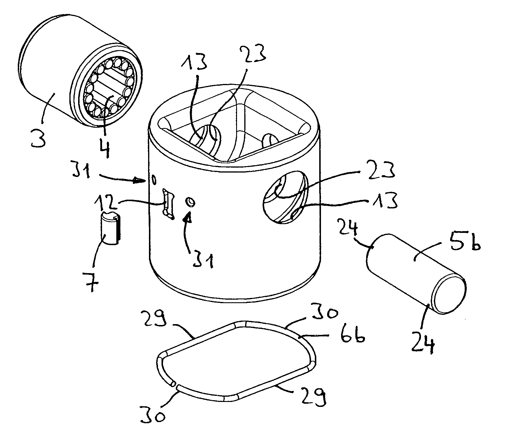
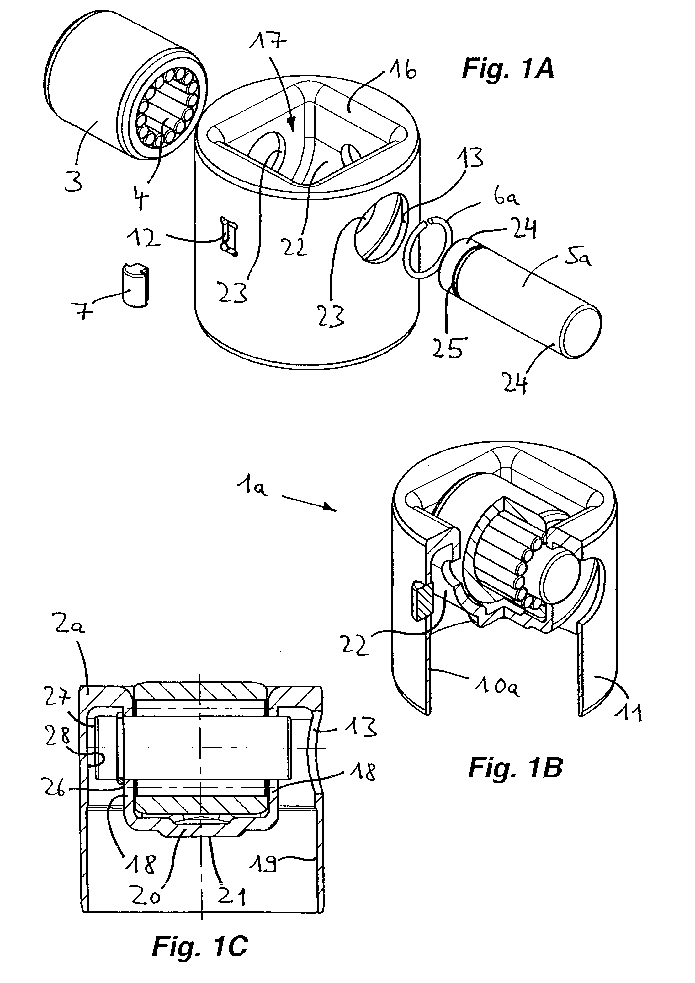
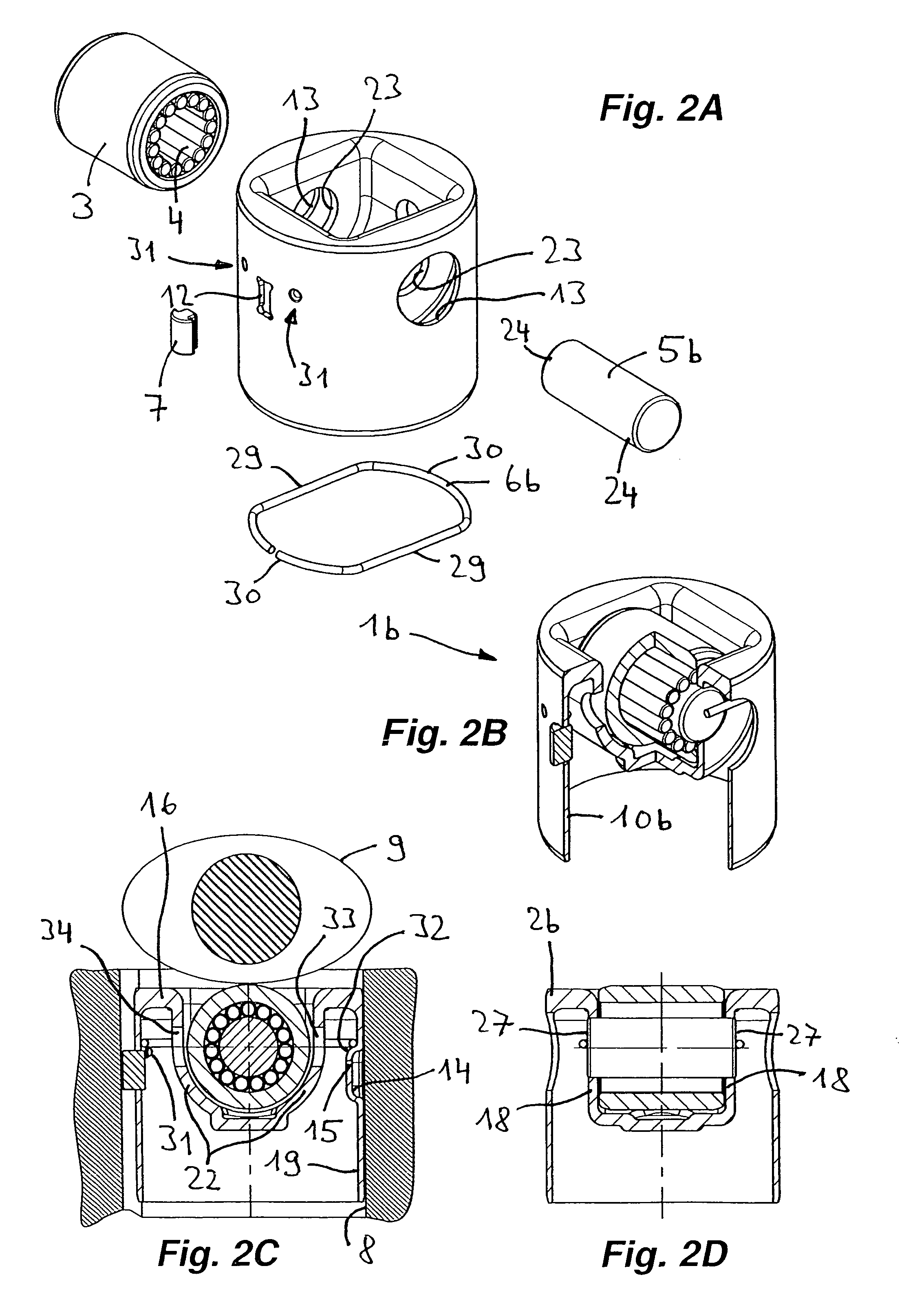
[0023]FIGS. 1A-1C illustrate a mechanical roller tappet 1a for lift actuation of a pump piston, not shown, of a high pressure fuel pump of an internal combustion engine. The roller tappet 1a comprises a one-piece, thin-walled tappet housing 2a shaped out of a sheet metal, a drive roller 3, an axle 5a which mounts the drive roller 3a centrally through rolling elements 4 configured as needle rollers, a locking ring 6a for axially fixing the axle 5a in the tappet housing 2a and an anti-rotation body 7 for a radial alignment of the drive roller 3 in a tappet guide and also for a parallel alignment of the drive roller 3 to a cam applying a lift to the drive roller 3. The tappet guide identified at 8 and the cam identified at 9 are illustrated in FIG. 2C.

[0024]The tappet housing 2a comprises a tappet skirt 10a comprising an outer peripheral surface 11 mounted for longitudinal displacement in the tappet guide 8. The outer peripheral surface 11 has a com...


PUM


Abstract

The invention proposes a mechanical roller tappet (1a, 1b) comprising a tappet housing (2a, 2b) shaped out of sheet metal, a drive roller (3) actuable by a cam (9) and an axle (5a, 5b) on which the drive roller (3) is mounted, end portions (24) of the axle (5a, 5b) being supported in axle eyes (23) of the tappet housing (2a, 2b), said tappet housing (2a, 2b) comprising a tappet skirt (10a, 10b) and a tappet bottom (16) possessing a contact surface (21) for an adjacent engine component on a power take-off side. At an end of the tappet skirt facing the cam, the tappet bottom is connected to the tappet skirt and is shaped into the interior of the tappet skirt while forming a pocket for receiving the drive roller, the axle eyes being arranged in first sections (18) of the tappet bottom while being spaced from an inner peripheral surface (19) of the tappet skirt and extending substantially parallel to the longitudinal direction of the tappet skirt, the contact surface being arranged on a second section (20) of the tappet bottom connecting the first sections to each other.

Description

FIELD OF THE INVENTION [0001]The invention concerns a mechanical roller tappet for an internal combustion engine, said roller tappet comprising a one-piece tappet housing shaped out of sheet metal, a drive roller actuable by a cam and an axle which mounts the drive roller centrally, optionally through rolling elements, end sections of the axle being supported in axle eyes of the tappet housing. The tappet housing comprises a tappet skirt which is mounted through an outer peripheral surface for longitudinal displacement in a tappet guide, and further comprises a tappet bottom possessing a contact surface for an adjacent engine component on a power take-off side.BACKGROUND OF THE INVENTION [0002]A roller tappet of the pre-cited type is disclosed in the document DE 100 44 732 A1 considered to be generic. The one-piece, shaped sheet metal tappet housing of the proposed roller tappet comprises a tappet skirt which, starting from a front-end tappet bottom, is configured with a semi-spheri...

Claims


Application Information

Patent Timeline
IPC IPC(8): F01L1/14
CPCF01L2107/00F01L1/143F01L1/08F01L2307/00
Inventor DORN, STEFANGEYER, NORBERTJANSEN, MANFREDKUCHT, KARSTENRADINGER, NORBERT
Owner SCHAEFFLER TECH AG & CO KG
Learn More