
Communication system, communication device, and communication method

a communication system and communication method technology, applied in the field of communication systems and communication devices, can solve the problems of congestion window immediately decreasing, unsent data units not included in congestion window, etc., and achieve the effect of reducing congestion, network load, and improving network performan

Inactive Publication Date: 2010-01-14
NTT DOCOMO INC
View PDF6 Cites 43 Cited by
  • Summary
  • Abstract
  • Description
  • Claims
  • Application Information

AI Technical Summary

Benefits of technology

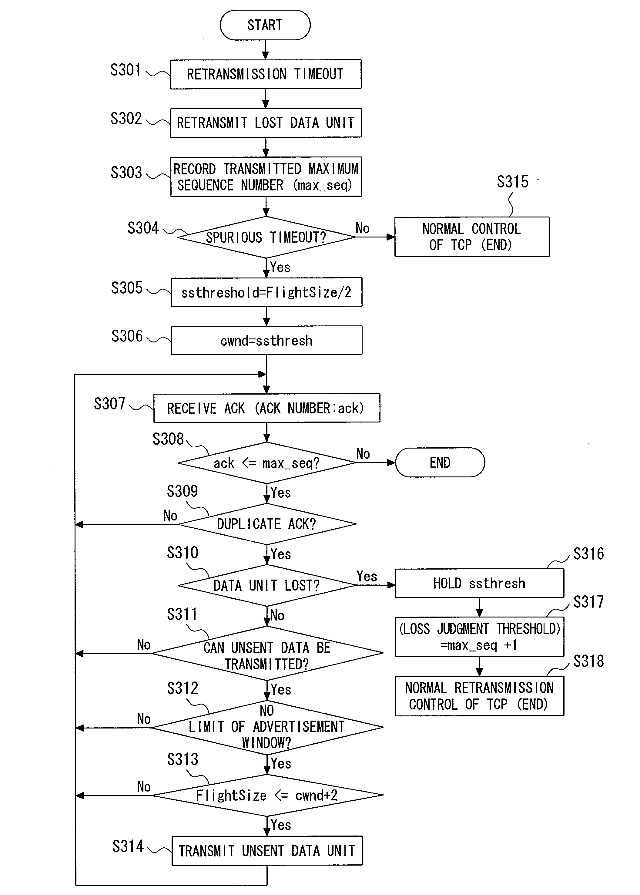
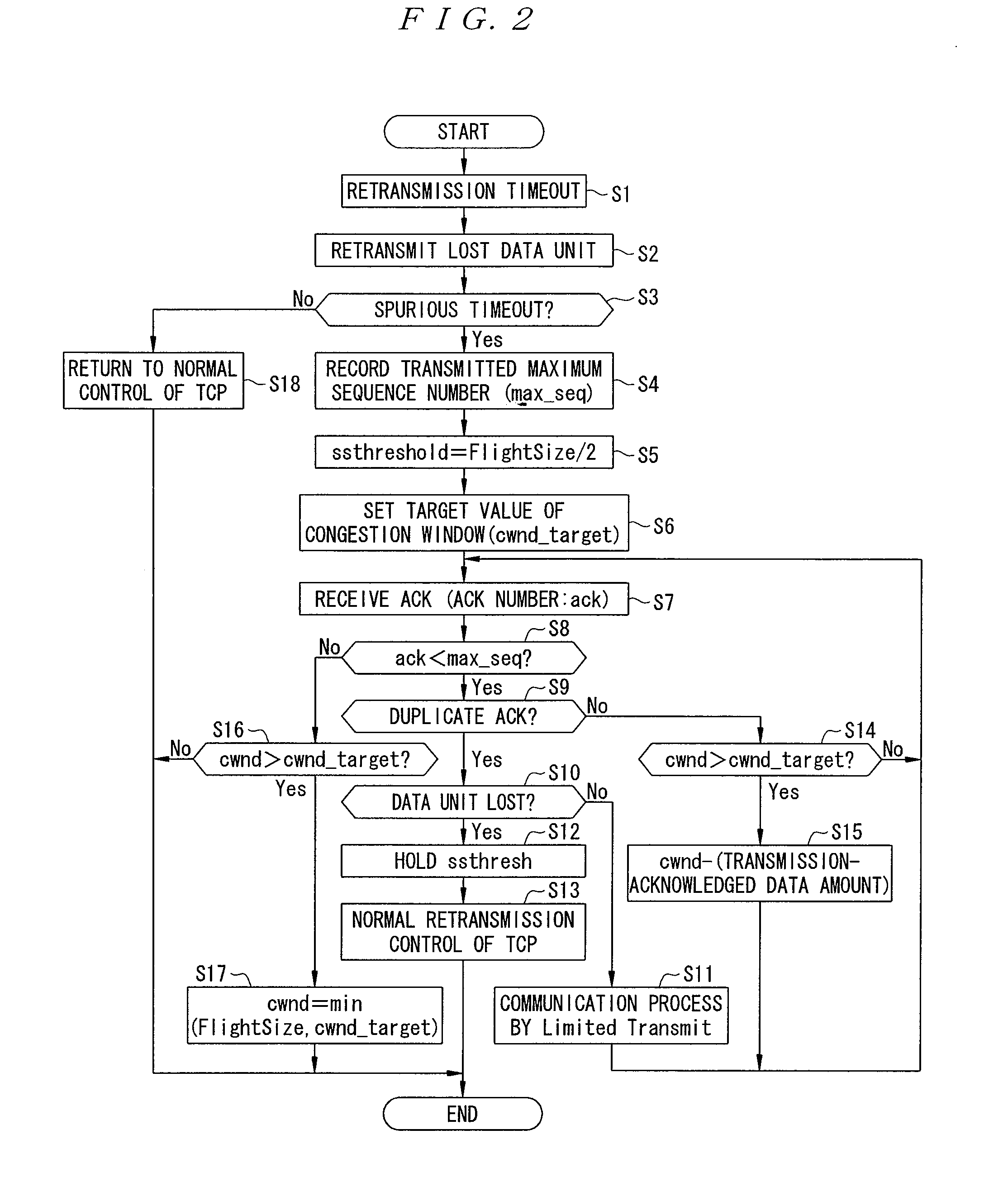
[0027]According to the configuration, a target value for decreasing the size of the congestion window is set in the transmitting / receiving device on the transmitting side when the spurious timeout has occurred. Subsequently, the size of the congestion window is gradually decreased to the target value when the acknowledgment response is received. Therefore, unsent data units (segments) can be transmitted with certainty, and as a result, efficient loss recovery is realized and the throughput is improved. Since the congestion window is immediately decreased to a large extent when the spurious timeout is detected in the conventional techniques, there is a situation in which unsent data units are not included in the congestion window. Therefore, unsent data units can not be transmitted when the first and second duplicate acknowledgment responses ACK are received.
[0065]Furthermore, since the operation realized using one threshold, the installation is facilitated.

Problems solved by technology

Since the congestion window is immediately decreased to a large extent when the spurious timeout is detected in the conventional techniques, there is a situation in which unsent data units are not included in the congestion window.

Method used


Image

  • Communication system, communication device, and communication method
  • Communication system, communication device, and communication method
  • Communication system, communication device, and communication method

Examples


first embodiment

[0082]A first embodiment of the present invention will now be described with reference to the drawings. In this regard, the corresponding parts are designated with the same reference numerals throughout the drawings in the present application, and the description of the overlapping parts will be appropriately omitted.

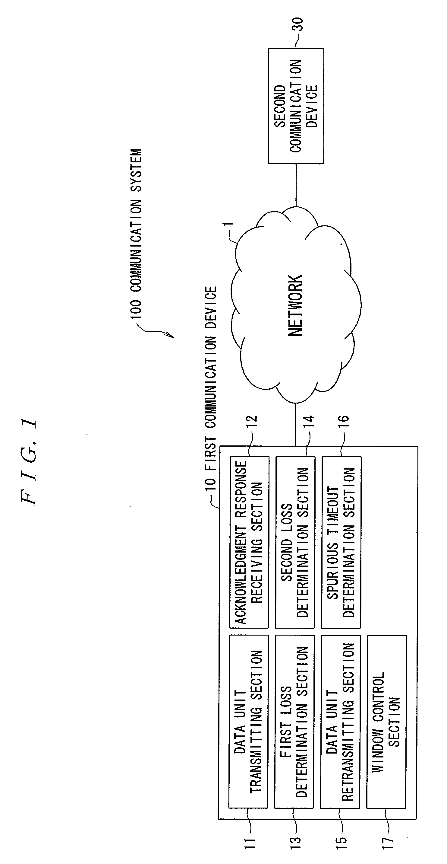
[0083]FIG. 1 is a block diagram of a configuration of a communication system according to the first embodiment of the present invention.

[0084]In the configuration of a communication system 100 illustrated in FIG. 1, a first communication device (communication device or transmitting / receiving device on the transmitting side) 10 and a second communication device (communication device or transmitting / receiving device on the receiving side) 30 are connected through a wireless and / or wired network 1. Although the first communication device 10 and the second communication device 30 are connected through one network 1 in the present embodiment, a plurality of networks may exis...

second embodiment

[0124]Next, a second embodiment of the present invention will be described.

[0125]FIG. 5 illustrates a block diagram of a configuration of a communication system according to the second embodiment of the present invention.

[0126]In the configuration of a communication system 200 shown in FIG. 5, a first communication device (transmitting device in this case) 40 and the second communication device (receiving device in this case) 30 are connected through the wireless and / or wired network 1. Although the first communication device 40 and the second communication device 30 are connected through the network 1 in the present embodiment, multiple networks may exist between the devices. The present invention works in an effective manner in a network in which signal delays suddenly increase. For example, the present invention is effective in a case where the network 1 is a mobile communication network. In this case, either or both of the first and second communication devices 40 and 30 corresp...

third embodiment

[0159]Next, a third embodiment of the present invention will be described.

[0160]FIG. 9 illustrates a block diagram indicative of a configuration of a communication system according to the third embodiment.

[0161]In the configuration of a communication system 300 illustrated in FIG. 9, a first communication device (transmitting device in this case) 50 and the second communication device (receiving device in this case) 30 are connected with each other through the wireless and / or wired network 1. Although the first communication device 50 and the second communication device 30 are connected with each other through the network 1 according to the present embodiment, multiple networks may exist between the devices. The present invention works in an effective manner in a network in which signal delays suddenly increase. For example, the present invention works in an effective manner in a case where the network 1 is a mobile communication network. In this case, either or both of the first an...


PUM


Abstract

A first loss determination section 13 of a first communication device 10 determines that a data unit is lost if an acknowledgment response for the transmitted data unit from a second communication device 30 is not received within a predetermined time and retransmits the data unit when the determination is made. When a determination section 16 determines that a spurious timeout has occurred, a window control section 17 sets a target value for decreasing the size of a congestion window and then gradually decreases the size of the congestion window to the target value when the acknowledgment response is received. Therefore, in a case of executing a response algorithm for changing a slow start threshold and the congestion window, if a segment loss occurs subsequent to the spurious timeout, an efficient loss recovery is achieved and the throughput is improved.

Description

TECHNICAL FIELD[0001]The present invention relates to a communication system, a communication device, and a communication method applied to communication or the like using a congestion control of TCP (Transmission Control Protocol) and wireless TCP.BACKGROUND ART[0002]In a conventional communication system, to ensure reliable transmission of either (or both) of a segment indicating arbitrary TCP / IP (Internet Protocol) data or ACK (ACKowledgment) packets of an acknowledgment response, the TCP includes a mechanism that sets a retransmission timer when transmitting the segment and that assumes the segment is lost and performs retransmission if the ACK is not sent back within the set time.[0003]However, in a communication environment with large delay variation such as mobile communication, the arrival of the ACK is delayed by a sudden increase of delays, and a retransmission timeout may occur although the segment is not lost. This is known as a spurious timeout.[0004]There are the follo...

Claims


Application Information

Patent Timeline
IPC IPC(8): H04L1/08G06F11/14H04L47/27
CPCH04L47/10H04L69/16H04L47/27H04L47/14H04W28/0242H04W28/10H04W8/04
Inventor YAMAMOTO, KAZUNORISUZUKI, HIDEHARU
Owner NTT DOCOMO INC
Learn More