
Stent-Graft Delivery System

a technology of stents and grafts, applied in the field of intravascular devices and methods, can solve the problems of significant deployment force required to retract, damage or destruction of stents, and failure of components of the delivery system, and achieve the effects of minimizing the deployment force of stents, normal force, and reducing the friction of graft-to-sheath friction

Active Publication Date: 2010-01-14
MEDTRONIC VASCULAR INC
View PDF30 Cites 49 Cited by
  • Summary
  • Abstract
  • Description
  • Claims
  • Application Information

AI Technical Summary

Benefits of technology

The present invention relates to a stent-graft delivery system and a method for delivering a stent-graft using the system. The technical effects of the invention include minimizing damage to the stent-graft and the delivery system during deployment, reducing the deployment force, and minimizing stress on the stent-graft and delivery system. The invention achieves these effects by using a retainer structure that automatically releases the stent-graft when the sheath is retracted, without requiring any additional manipulations by the physician. The retainer release trigger includes a pull rod portion or a trigger portion that extends radially from the lumen through the trigger aperture.

Problems solved by technology

However, prior to deployment, the compressed stent-graft tends to press outwards on the inner surface of the sheath because of its high radial force, self-expanding design.
As a result, significant deployment force is required to retract the sheath to deploy the stent-graft.
This significant deployment force puts significant stress on the stent-graft, which can result in damage or destruction of the stent-graft during deployment.
Further, this significant deployment force places significant stress on the delivery system, which can lead to component failure of the delivery system.

Method used


Image

  • Stent-Graft Delivery System
  • Stent-Graft Delivery System
  • Stent-Graft Delivery System

Examples


Embodiment Construction

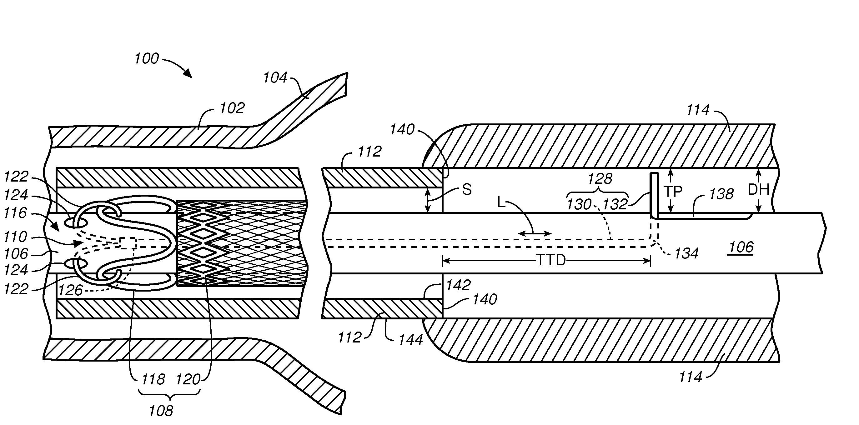
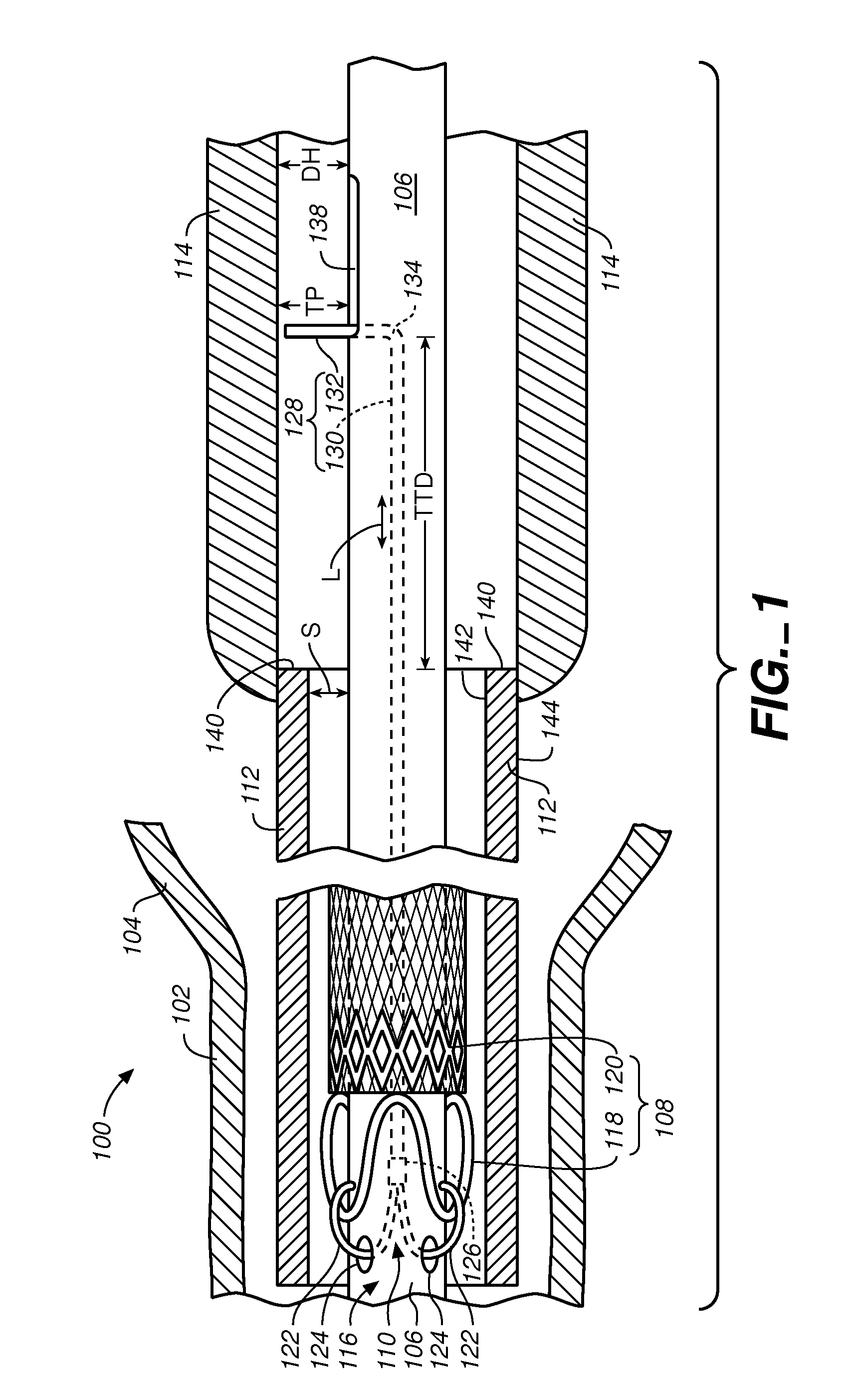
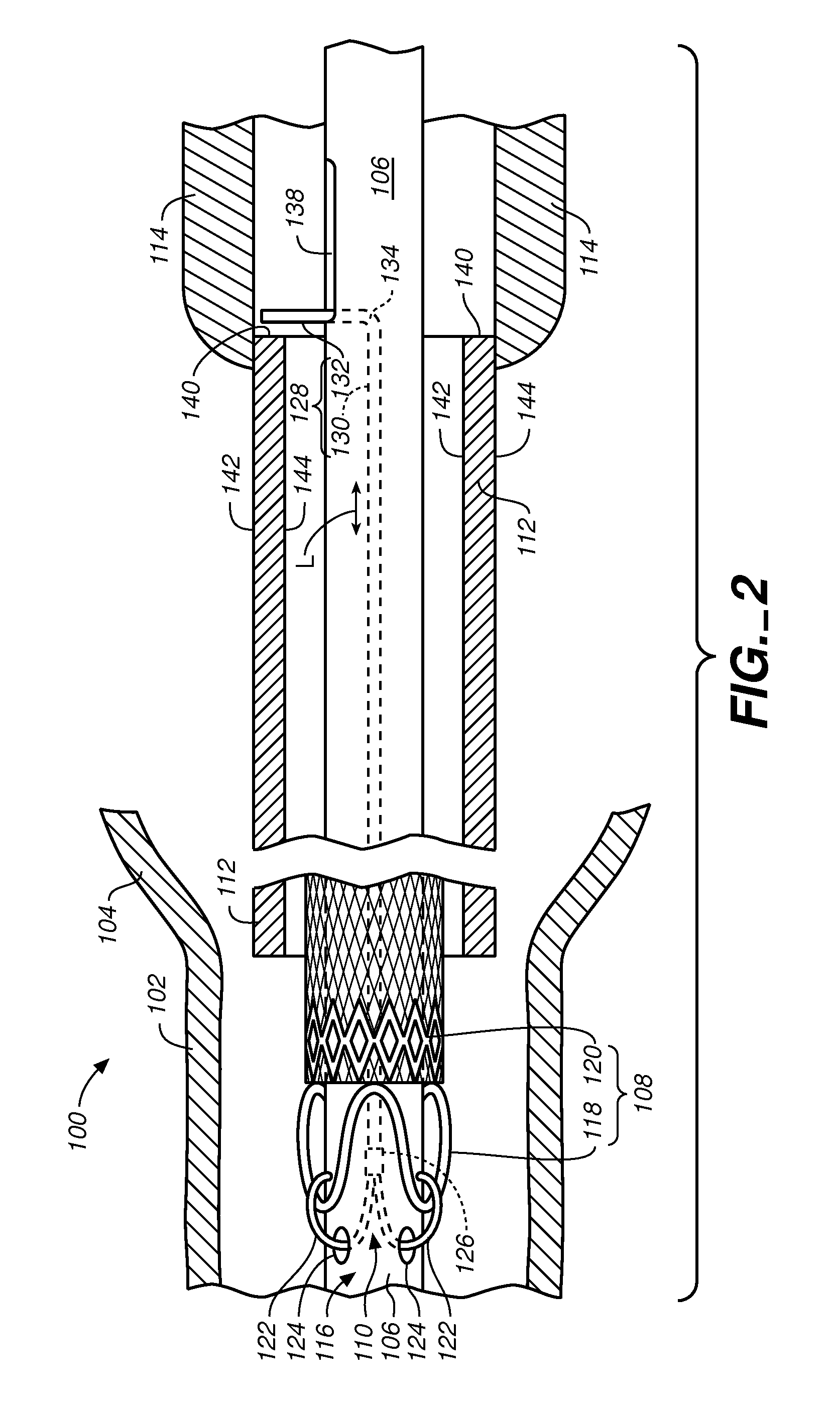
[0023]In one embodiment according to the present invention, a method of delivering a stent-graft 108 includes mounting stent-graft 108 on a pushrod 106 (FIG. 1); radially constraining stent-graft 108 within a sheath 112; securing a crown portion 118 of stent-graft 108 to pushrod 106 with a retainer structure 122 of a stent-graft retainment system 110; retracting sheath 112 to expose crown portion 118 of stent-graft 108 (FIG. 2); and further retracting sheath 112 to cause retainer structure 122 to release crown portion 118 from pushrod 106 thus deploying stent-graft 108 (FIG. 3).

[0024]Retainer structure 122 releases stent-graft 108 automatically as a result of the retraction of sheath 112. Thus, exposure of crown portion 118 by sheath 112 (FIG. 2) followed by release of crown portion 118 by retainer structure 122 (FIG. 3) does not require any additional manipulations by the physician compared to a conventional stent-graft delivery system.

[0025]More particularly, FIG. 1 is a modified ...


PUM


Abstract

A method of delivering a stent-graft includes mounting the stent-graft on a pushrod; radially constraining the stent-graft within a sheath; securing a crown portion of the stent-graft to the pushrod with a retainer structure of a stent-graft retainment system; retracting the sheath to expose the crown portion of the stent-graft; and further retracting the sheath to cause the retainer structure to release the crown portion from the pushrod thus deploying the stent-graft. The retainer structure releases the stent-graft automatically as a result of the retraction of the sheath.

Description

BACKGROUND OF THE INVENTION[0001]1. Field of the Invention[0002]The present invention relates to an intra-vascular device and method. More particularly, the present invention relates to a device for deployment of a stent-graft for treatment of intra-vascular aneurysms.[0003]2. Description of the Related Art[0004]In stent-graft deployment systems, a self-expanding stent-graft is restrained within a sheath. After placement of the stent-graft at the desired location via fluoroscopic guidance, the physician retracts the sheath to deploy the stent-graft, i.e., to expose the stent-graft and allow it to self-expand.[0005]However, prior to deployment, the compressed stent-graft tends to press outwards on the inner surface of the sheath because of its high radial force, self-expanding design. As a result, significant deployment force is required to retract the sheath to deploy the stent-graft.[0006]This significant deployment force puts significant stress on the stent-graft, which can result...

Claims


Application Information

Patent Timeline
Patent Type & Authority Applications(United States)
IPC IPC(8): A61F2/06A61F2/84
CPCA61F2/962A61F2002/9505A61F2002/9665A61F2002/9517A61F2002/9511A61F2/966A61F2/9517
Inventor GOODSON IV, HARRY B.ELKINS, JEFF
Owner MEDTRONIC VASCULAR INC
Learn More