
Method for light emitting diode control and corresponding light sensor array, backlight and liquid crystal display

a technology of light emitting diodes and control methods, applied in lighting apparatuses, light sources, instruments, etc., can solve the problems of significant cost, significant amount of components, and inability to produce light inherently

Inactive Publication Date: 2010-01-14
KONINKLIJKE PHILIPS ELECTRONICS NV
View PDF9 Cites 52 Cited by
  • Summary
  • Abstract
  • Description
  • Claims
  • Application Information

AI Technical Summary

Benefits of technology

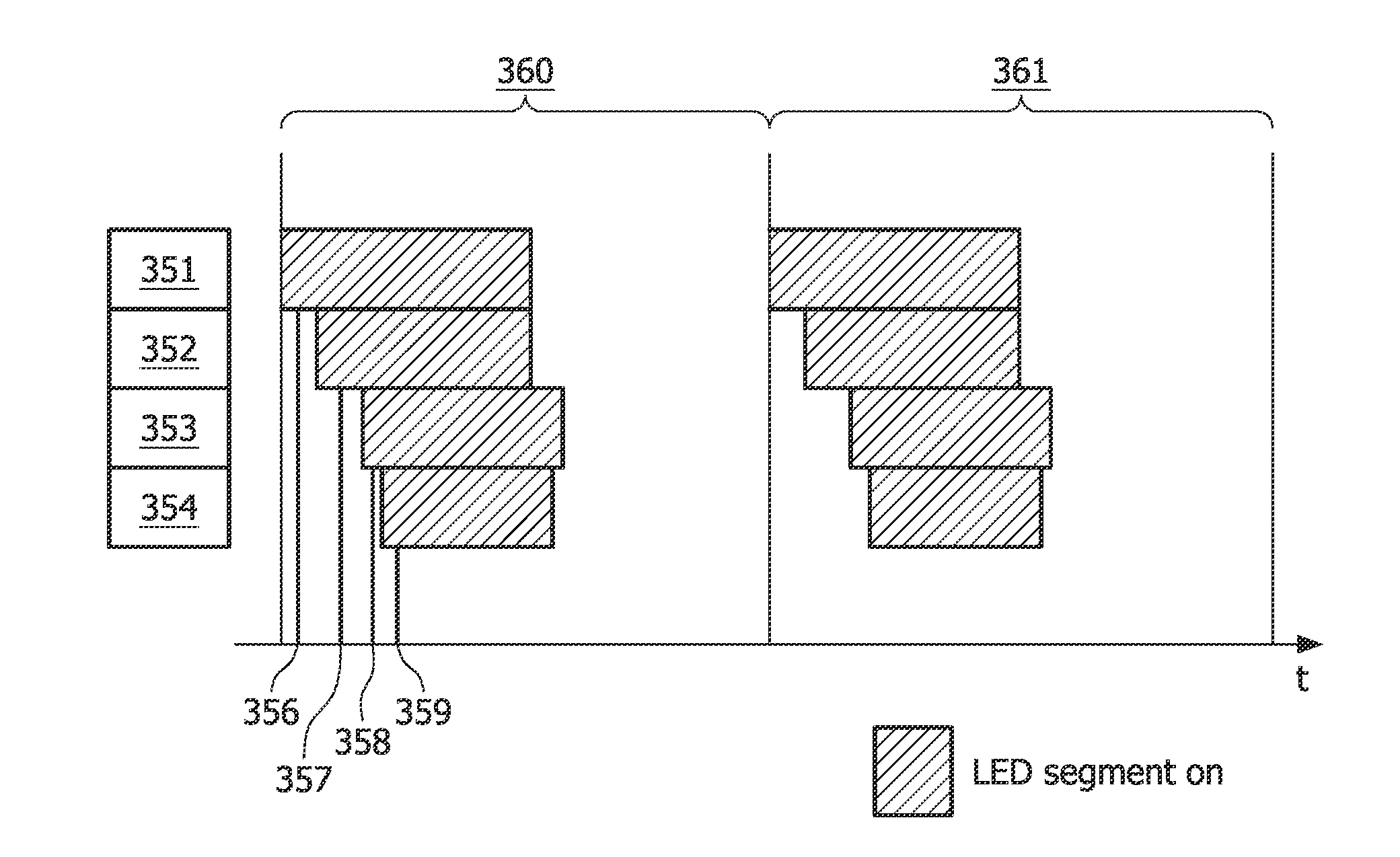
[0006]Generally, the above objectives are achieved by the attached independent patent claims. A first aspect of the invention is a method for controlling a light level of light emitting diodes, LEDs, comprised in a light sensor segment comprising a light sensor and a plurality of LEDs, the method comprising the steps of: turning on all LEDs in an LED segment, comprising at least one of the plurality of LEDs, detecting a light level associated with the LED segment, by detecting a light level using the light sensor, repeating the steps of turning on all LEDs in an LED segment and detecting a light level, until all of the plurality of LEDs are turned on, and for each LED of the plurality of LEDs, controlling a light intensity of the each LED of the plurality of LEDs, the intensity control depending on the detected light level associated with an LED segment containing the each LED of the plurality of LEDs. With such a method, a feedback loop is achieved, whereby color and intensity are controlled efficiently.
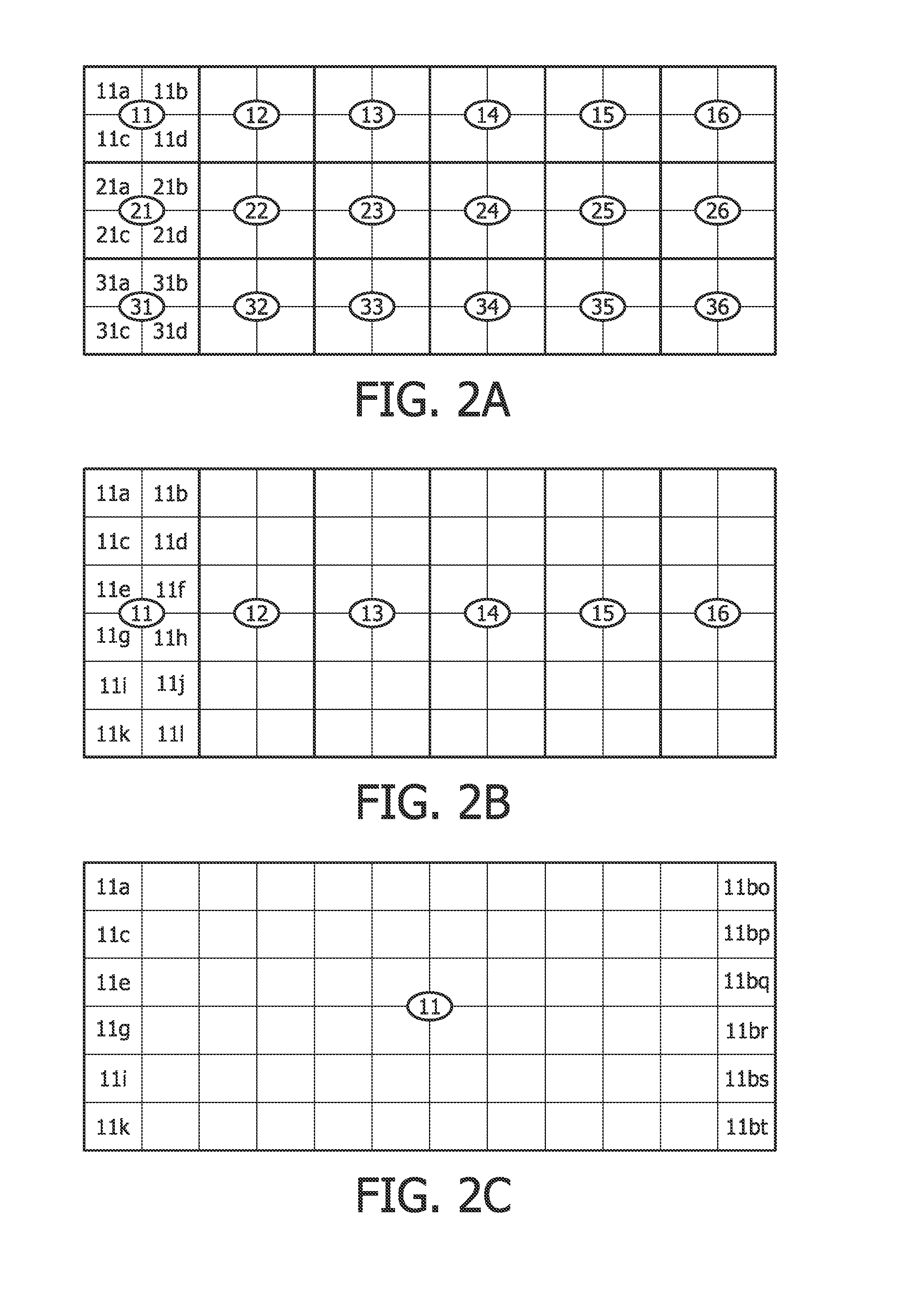
[0009]The step of turning on all LEDs in an LED segment may involve turning on all LEDs in the LED segment, the LED segment comprising at least a red, a green and a blue LED, and the step of detecting a light level associated with the LED segment may involve detecting a light level associated with the LED segment, by detecting at least three separate light levels using the light sensor capable of detecting at least red, green and blue light independently, the at least three light levels being associated with the at least red, green and blue LEDs, respectively. This provides an efficient use in the time domain, as only one light sensor is used, allowing the light level for the different colors to be measured in the same time period.
[0010]The step of turning on all LEDs in an LED segment may involve turning on one LED of the plurality of LEDs, the one LED constituting the LED segment, the one LED having one color. This allows all colors to be independently measured, whereby there is no need for a light sensor capable of independently detecting light levels of different colors.
[0020]The light sensor segment may further comprise a reflecting surface, and the light sensor may be arranged by an opening of the reflecting surface on one side of the reflecting surface and the LEDs may be configured to project light to a second side of the reflecting surface. In other words, the sensor is behind holes the reflecting surface from where the light is projected. The amount of light provided to the sensor is thus increased.
[0026]The backlight for a display system may further comprise at least one pin hole array arranged such that light sensors of the light sensor segments are located on a first side of the at least one pin hole array and LEDs of the light sensor segments may be configured to project light on a second side of the at least one pin hole array, the at least one pin hole array restricting a sensor direction for detecting light for each of the light sensors. This provides better control on what light directions are allowed to affect the light detected by the light sensor.

Problems solved by technology

Rendering of images using LCDs in LCD televisions however, does not produce light inherently and requires either reflected light from the room or, more commonly, a light source for the user to be able to view the video image with sufficient light intensity.
This is a challenge because the output of LEDs changes strongly when their temperature rises, but also during ageing.
Controlling color over time requires a significant amount of components, resulting in a significant cost.

Method used


Image

  • Method for light emitting diode control and corresponding light sensor array, backlight and liquid crystal display
  • Method for light emitting diode control and corresponding light sensor array, backlight and liquid crystal display
  • Method for light emitting diode control and corresponding light sensor array, backlight and liquid crystal display

Examples


Embodiment Construction

[0039]The present invention will now be described more fully hereinafter with reference to the accompanying drawings, in which certain embodiments of the invention are shown. This invention may, however, be embodied in many different forms and should not be construed as limited to the embodiments set forth herein; rather, these embodiments are provided by way of example so that this disclosure will be thorough and complete, and will fully convey the scope of the invention to those skilled in the art. Like numbers refer to like elements throughout.

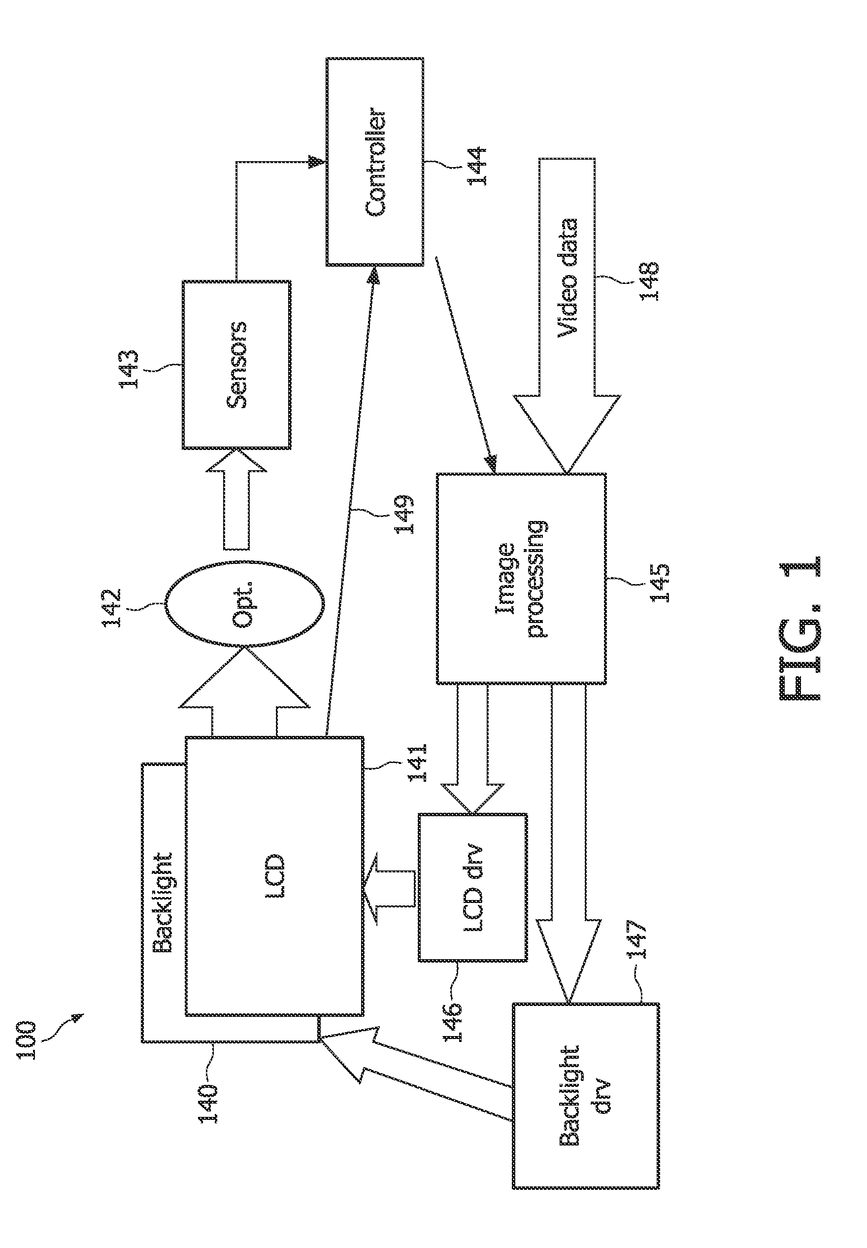
[0040]FIG. 1 is schematic diagram showing relevant components of an LCD (liquid crystal display) television 100 where the present invention is embodied.

[0041]Video data 148 is fed from a suitable source, e.g. television tuner (analogue or digital), DVD player, video game console, VCR, computer, etc. The video data 148 is received in an image processing module 145, which divides the video signal in a signal to an LCD driver module 146 and a ...


PUM


Abstract

It is presented a method for controlling a light level of light emitting diodes, LEDs, comprised in a light sensor segment comprising a light sensor and a plurality of LEDs, the method comprising the steps of: turning on all LEDs in an LED segment, comprising at least one of the plurality of LEDs, detecting a light level associated with the LED segment, by detecting a light level using the light sensor, repeating the steps of turning on all LEDs in an LED segment and detecting a light level, until all of the plurality of LEDs are turned on, and for each LED of the plurality of LEDs, controlling a light intensity of the each LED of the plurality of LEDs, the intensity control depending on the detected light level associated with an LED segment containing the each LED of the plurality of LEDs. A corresponding light sensor array, backlight for a display system and liquid crystal display are also presented.

Description

FIELD OF THE INVENTION[0001]The present invention relates to light emitting diodes and more particularly to controlling a light level of light emitting diodes.BACKGROUND OF THE INVENTION[0002]Light Emitting Diodes (LEDs) can be used for many purposes. One such purpose is to provide backlighting for Liquid Crystal Display (LCD) televisions. With other television technologies, light is often generated as part of the image rendering. For example, in Cathode Ray Tube (CRT) televisions, electrons are shot on a fluorescent screen to render a video image to the user, whereby light is generated in the same process as the video image is rendered. Rendering of images using LCDs in LCD televisions however, does not produce light inherently and requires either reflected light from the room or, more commonly, a light source for the user to be able to view the video image with sufficient light intensity.[0003]Traditionally, fluorescent tubes are used as backlight in LCD displays, but lately LEDs ...

Claims


Application Information

Patent Timeline
IPC IPC(8): G09G3/36H05B37/02G09G3/32
CPCG02F1/133603G09G2360/145G09G3/3426
Inventor DEURENBERG, PETER HUBERTUS FRANCISCUSPEETERS, HENRICUS MARIEVAN AS, MARCOHOELEN, CHRISTOPH GERARD AUGUST
Owner KONINKLIJKE PHILIPS ELECTRONICS NV
Learn More