
Imaging of turbid medium

a technology of turbid medium and imaging device, which is applied in the field of imaging device of turbid medium, can solve the problem that patients will always need to lie down, and achieve the effect of versatile matching fluid and sufficient optical density

Inactive Publication Date: 2010-01-07
KONINKLIJKE PHILIPS ELECTRONICS NV
View PDF13 Cites 2 Cited by
  • Summary
  • Abstract
  • Description
  • Claims
  • Application Information

AI Technical Summary

Benefits of technology

[0006]The present invention addresses the above needs by providing an improved way of imaging turbid medium, and preferably, the invention alleviates, mitigates or eliminates one or more of the above or other disadvantages singly or in any combination. To this end, the inventors have had the insight that, until now, liquid media have been used as adaptation medium for matching the optical properties of the adaptation medium and the turbid medium.
[0013]The invention is particularly, but not exclusively advantageous, for providing a device which solves the short-circuit problem in connection with imaging of turbid medium, which maintains most if not all of the advantages of using a liquid matching fluid, and which moreover allows the patient to sit or stand during the measurement.
[0015]To this end, the optical properties of the vapor can be controlled in a number of ways, advantageous embodiments are provided in the dependent claims. It is an advantage that the optical properties of the vapor can be adjusted and controlled in a number of ways, thereby rendering possible a versatile matching fluid.
[0017]In an advantageous embodiment the device may further comprise a device for generating sound waves for randomizing the position of the particles in the vapor. It is an advantage to randomize the position of the particles in order to stabilize the optical properties of the matching fluid on the time-scale of a measurement.

Problems solved by technology

A drawback of this method is that the patient will always need to lie down, because the measurement can only be done with the breast hanging down into the liquid, since otherwise the liquid will leak out.
A general problem with absorbing / scattering liquids, is that the scattering / absorbing particles within the liquid will be pulled down by gravity and hence need to be stabilized to prevent settling of the particles on the bottom.

Method used


Image

  • Imaging of turbid medium
  • Imaging of turbid medium
  • Imaging of turbid medium

Examples


Embodiment Construction

[0031]One of the challenges for optical mammography is to prevent light from finding a path from the light source to the detector without traveling through the tissue under investigation, i.e. to solve the short-circuit problem.

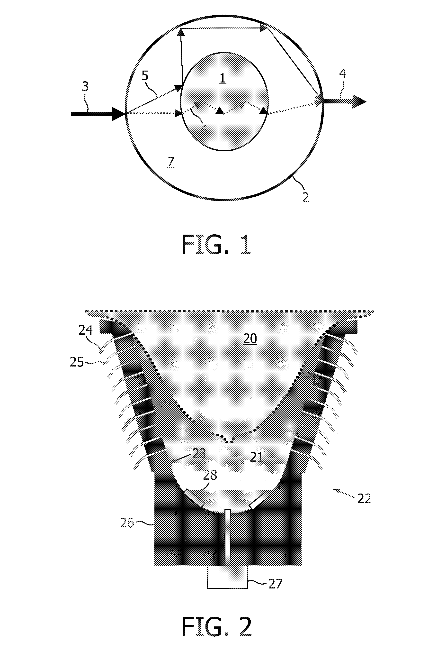
[0032]FIG. 1 illustrates the short-circuit problem present in optical mammography. The tissue under investigation, i.e. the turbid medium 1, being a female breast or part of the breast is put inside a holder 2, also often referred to as a cup. The holder also contains the optics, being a light source 3 and detector 4 (or number of light sources and detectors). The solid line 5 shows a path from source 3 to detector 4 traveling around the tissue under investigation. The problem with this is that the small fraction of the light reaching the detector that has traveled through the tissue, as illustrated by the broken line 6, is masked by the comparatively large amount of light which has reached the detector by traveling around the tissue under investigation.

[0033...


PUM

PropertyMeasurementUnit
refractive indexaaaaaaaaaa
scattering coefficientsaaaaaaaaaa

Abstract

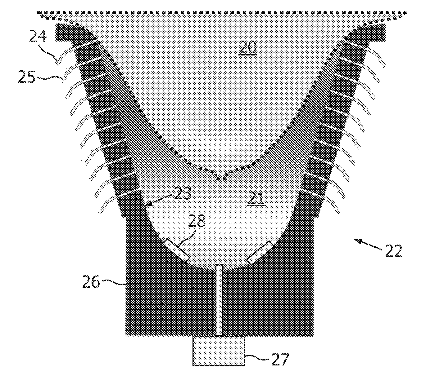
The invention relates to imaging of a turbid medium, for example in connection with optical mammography. A device for imaging a turbid medium (20) is disclosed, the device comprising: a holder (20) arranged for receiving the turbid medium and a matching fluid (21); one or more radiation sources (24) and one or more photodetectors (25). The matching fluid is a vapor with one or more optical properties of the matching fluid substantially matching the corresponding one or more optical properties of the turbid medium. In an embodiment, the matching fluid (21) is a composite vapor comprising at least two components.

Description

FIELD OF THE INVENTION[0001]The invention relates to a device for imaging a turbid medium, and in particular by imaging the turbid medium by means of optical radiation. Moreover, the invention relates to a method of imaging a turbid medium.BACKGROUND OF THE INVENTION[0002]A number of devices for imaging the internal structure of human or animal tissue exists, a type of such devices pertains to optical mammography for in vivo examinations of breast tissue of a human or animal female. In this case, the turbid medium is the breast of the female to be examined.[0003]In known types of optical mammography devices, the breast or part of the breast is put inside a holder including a number of light sources and photodetectors which are distributed across the wall of the holder. The holder moreover contains a matching liquid in which the breast is immersed. The matching liquid provides optical coupling between the part of the breast to be imaged and the light sources and the photodetectors, r...

Claims


Application Information

Patent Timeline
Patent Type & Authority Applications(United States)
IPC IPC(8): A61B5/00G01N21/00
CPCA61B5/0091G01N21/4795A61B2562/146A61B5/4312
Inventor VAN HERPEN, MAARTEN MARINUS JOHANNES WILHELMVAN DER MARK, MARTINUS BERNARDUSVAN BEEK, MICHAEL CORNELIS
Owner KONINKLIJKE PHILIPS ELECTRONICS NV
Learn More