
Display panel, multi-layer display element, and method of fabricating the same

a display element and multi-layer technology, applied in the field of multi-layer display elements, can solve the problems of reducing the sharpness of text and images, reducing the alignment position of individual display panels, and not allowing the light transmisive sta

Inactive Publication Date: 2010-01-07
FUJITSU LTD
View PDF1 Cites 38 Cited by
  • Summary
  • Abstract
  • Description
  • Claims
  • Application Information

AI Technical Summary

Benefits of technology

[0019]It is an object of the invention is to provide a display panel, a multi-layer display element, and a method of fabricating the same, which can readily align the alignment positions of individual display panels with each other even though common alignment marks are provided on each of the display panels.
[0038]According to the invention, such a display panel and a multi-layer display element can be implemented, which can readily align the alignment positions of the individual display panels with each other even though common alignment marks are provided on each of the display panels.

Problems solved by technology

On the other hand, except the liquid crystal type and the electrochemical type, the other types do not allow the light transmissive state.
When the positions of the display panels in the in-plane direction are displaced, the alignment positions of the pixels are misaligned to cause color shift or the degradation of brightness, which leads to a reduced sharpness of the edges of text and images.
On this account, it is difficult to obtain excellent display quality.
However, when alignment marks in the same shape are formed on each of the display panels, it is difficult to distinguish between a plurality of the alignment marks laid on each other which alignment mark corresponds to which one of upper and lower display panels.
Therefore, extra work is required to suffer working efficiency.
Moreover, also in the case in which alignment marks are imaged by a CCD (Charge-Coupled Device) camera to subject the taken image to image processing for detecting the positions of the alignment marks, it is difficult to distinguish between the alignment marks laid on each other, and it is not easy to match alignment positions with each other.
On this account, when the thickness of two display panels placed in layers is increased, it is difficult to visually recognize alignment marks at the same time, which leads to a degraded position accuracy of alignment positions, or to longer work hours required for alignment work.
In both of the methods, because the alignment marks are formed of a transparent electrode material, the contrast becomes low to cause insufficient visibility.
However, because it is necessary to apply voltage to the electrodes, a circuit for voltage application has to be wired to the terminals of the electrodes, which decreases working efficiency in preparing the display panel.

Method used


Image

  • Display panel, multi-layer display element, and method of fabricating the same
  • Display panel, multi-layer display element, and method of fabricating the same
  • Display panel, multi-layer display element, and method of fabricating the same

Examples


first embodiment

[0057]A display panel, a multi-layer display element, and a method of fabricating the same according to a first embodiment of the invention will be described with reference to FIGS. 1 to 9.

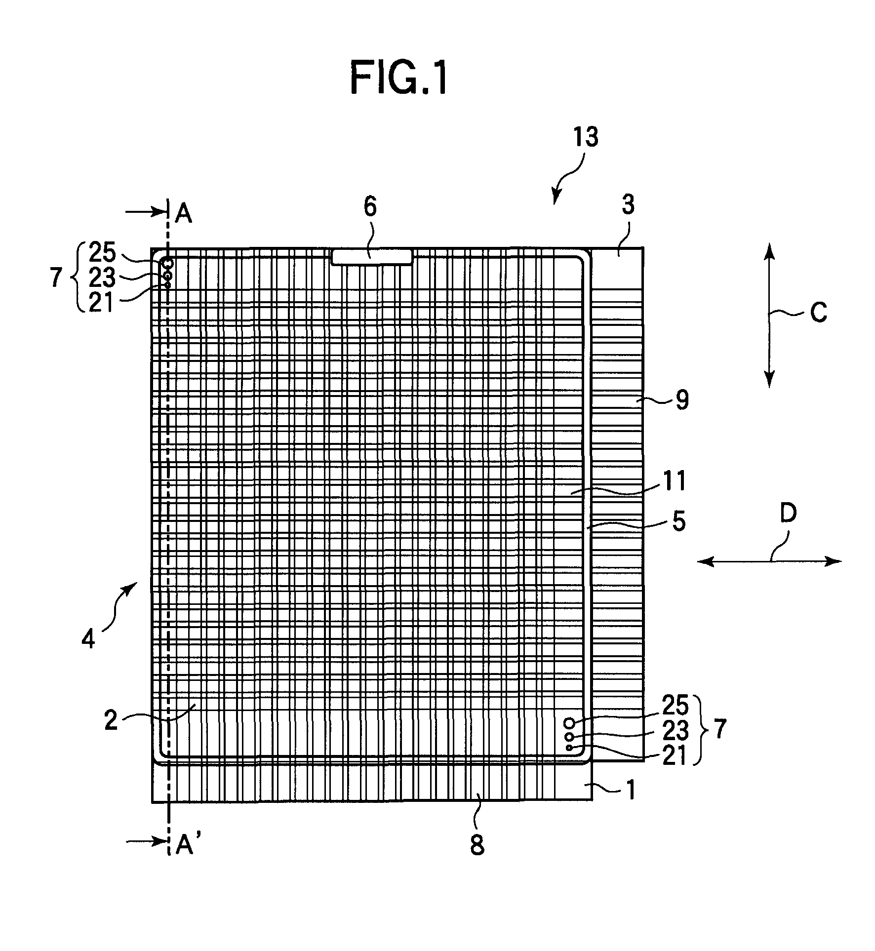
[0058]FIG. 1 is a plan view depicting a display panel of this embodiment when seen from the display surface side. FIG. 2 is a cross section depicting the cross-sectional configuration cut at line A-A shown in FIG. 1.

[0059]A display panel 13 of the embodiment is used mainly as placed in layers. For example, three display panels 13, which can display blue, green and red, are placed in layers, whereby color representation is allowed.

[0060]As shown in FIG. 1, the display panel 13 is formed in a rectangular plate shape, and a pixel area 4, which can display images, is provided in the center. The display panel 13 has a pair of rectangular glass substrates 1 and 3, a sealing wall 5, a display material layer 11, and an alignment mark group 7.

[0061]As shown in FIG. 2, the paired glass substrates 1 and 3 ar...

second embodiment

[0130]A multi-layer display element according to a second embodiment of the invention will be described with reference to FIGS. 14 to 16.

[0131]A multi-layer display element 200 of the embodiment has almost the same configuration as that of the multi-layer display element 100 of the first embodiment, and it is different in the material of a substrate to form display panels and the layered state of the display panels. Hereinafter, common components are designated the same numerals and signs, and the descriptions are omitted.

[0132]FIG. 14 is a cross section depicting the multi-layer display element of the second embodiment.

[0133]Display panels 213B, 213G, and 213R of the embodiment each have a pair of rectangular resin substrates 201 and 203.

[0134]In the substrates 201 and 203 using resin, it is difficult to maintain the interval between the resin substrate 201 and the resin substrate 203 almost constantly. Thus, a spacer 28 in a rib structure (a partition structure) is formed between ...


PUM


Abstract

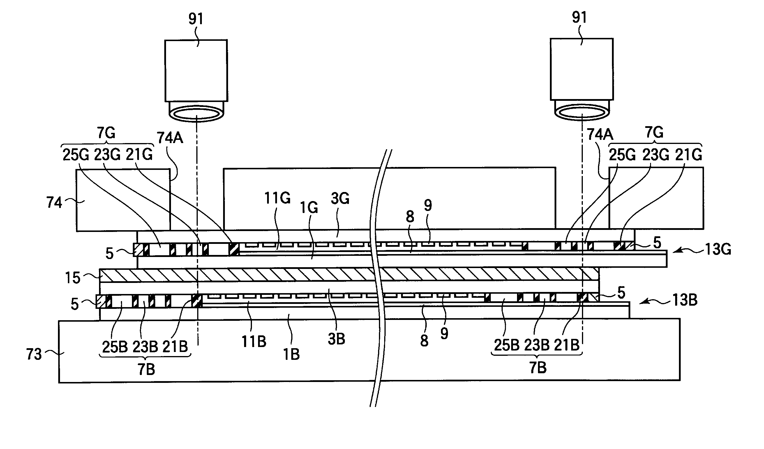
The present invention is to provide a display panel, a multi-layer display element, and a method of fabricating same, which can readily align alignment positions of individual display panels with each other even though common alignment marks are provided on each of display panels. A display panel includes a pair of substrates faced to each other as a display material layer is sandwiched between the substrates, a plurality of pixels provided in a plane almost in parallel with a substrate surface between the substrates, and a plurality of alignment marks formed in different shapes and linearly arranged on at least one of the pair of the substrates at a predetermined interval for alignment in placing the display panels in layers.

Description

[0001]This Application is a continuation of International Application No. PCT / JP2007 / 055244, filed Mar. 15, 2007.BACKGROUND OF THE INVENTION[0002]1. Field of the Invention[0003]The present invention relates to a multi-layer display element having a plurality of display panels placed in layers, and a method of fabricating the same.[0004]2. Description of the Related Art[0005]In the future, it is expected that electronic paper rapidly spreads, which can hold display images with no power supply and electrically rewrite a display content. Electronic paper is under development with the aim of realizing ultralow power consumption enabling memory display even though a power supply is turned off, reflective display easy on the eyes with no fatigue, and a flexible, low-profile display body with flexibility like paper. As the applications of electronic paper, electronic books, electronic newspapers, and electronic poster are proposed.[0006]Depending on the differences of display types, electr...

Claims


Application Information

Patent Timeline
IPC IPC(8): G02F1/1333H01J9/20
CPCG02F1/1303G02F2001/13478G02F2001/133354G02F1/1347G02F1/133354G02F1/13478
Inventor FUKUDA, MAKOTO
Owner FUJITSU LTD
Learn More