
Carbon nanotube-based coaxial electrical cables and wiring harness

a technology of carbon nanotubes and coaxial cables, applied in the field of cable formation, can solve the problems of affecting the overall reaction kinetics and blocking the exit of nanomaterials from the chamber, and achieve the effect of enhancing conductivity

Active Publication Date: 2010-01-07
NANCOMP TECHNOLOGIES INC
View PDF95 Cites 89 Cited by
  • Summary
  • Abstract
  • Description
  • Claims
  • Application Information

AI Technical Summary

Benefits of technology

[0011]The present invention provides, in accordance with one embodiment, a cable. In an embodiment, the cable may include a conducting member made from a nanostructure-based material, a shielding layer made of nanostructure-based material and circumferentially situated about the conducting member so as to enhance conductivity along the conducting member, and a coupling mechanism situated between the shielding layer and the conducting member so as to secure the shielding layer in its position on the conducting member.
[0012]The present invention provides, in accordance with another embodiment, a method for making a cable. The method may include providing a conducting member made from a nanostructure-based material, placing a shielding layer circumferentially about the conducting member, and applying a coupling mechanism between the shielding layer and the conducting member so as to secure the shielding layer in its position about the conducting member.

Problems solved by technology

In cases where large volumes of carbon nanotubes may be generated, however, the nanotubes may attach to the walls of a reaction chamber, resulting in the blockage of nanomaterials from exiting the chamber.
Furthermore, these blockages may induce a pressure buildup in the reaction chamber, which can result in the modification of the overall reaction kinetics.
An additional concern with nanomaterials may be that they need to be handled and processed without generating large quantities of airborne particulates, since the hazards associated with nanoscale materials are not yet well understood.

Method used


Image

  • Carbon nanotube-based coaxial electrical cables and wiring harness
  • Carbon nanotube-based coaxial electrical cables and wiring harness
  • Carbon nanotube-based coaxial electrical cables and wiring harness

Examples


Embodiment Construction

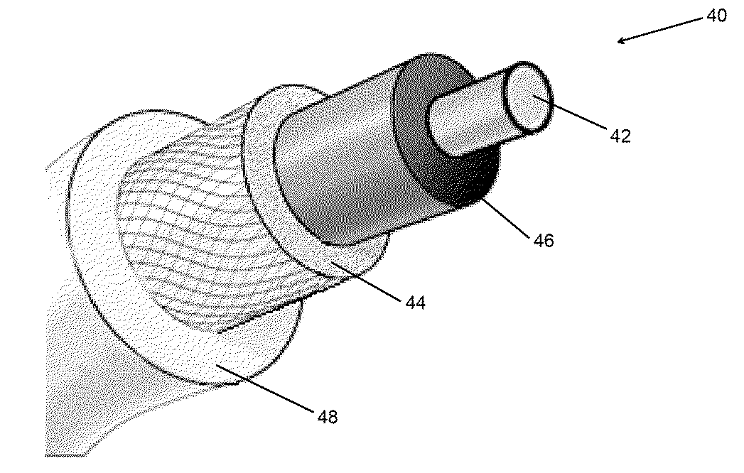
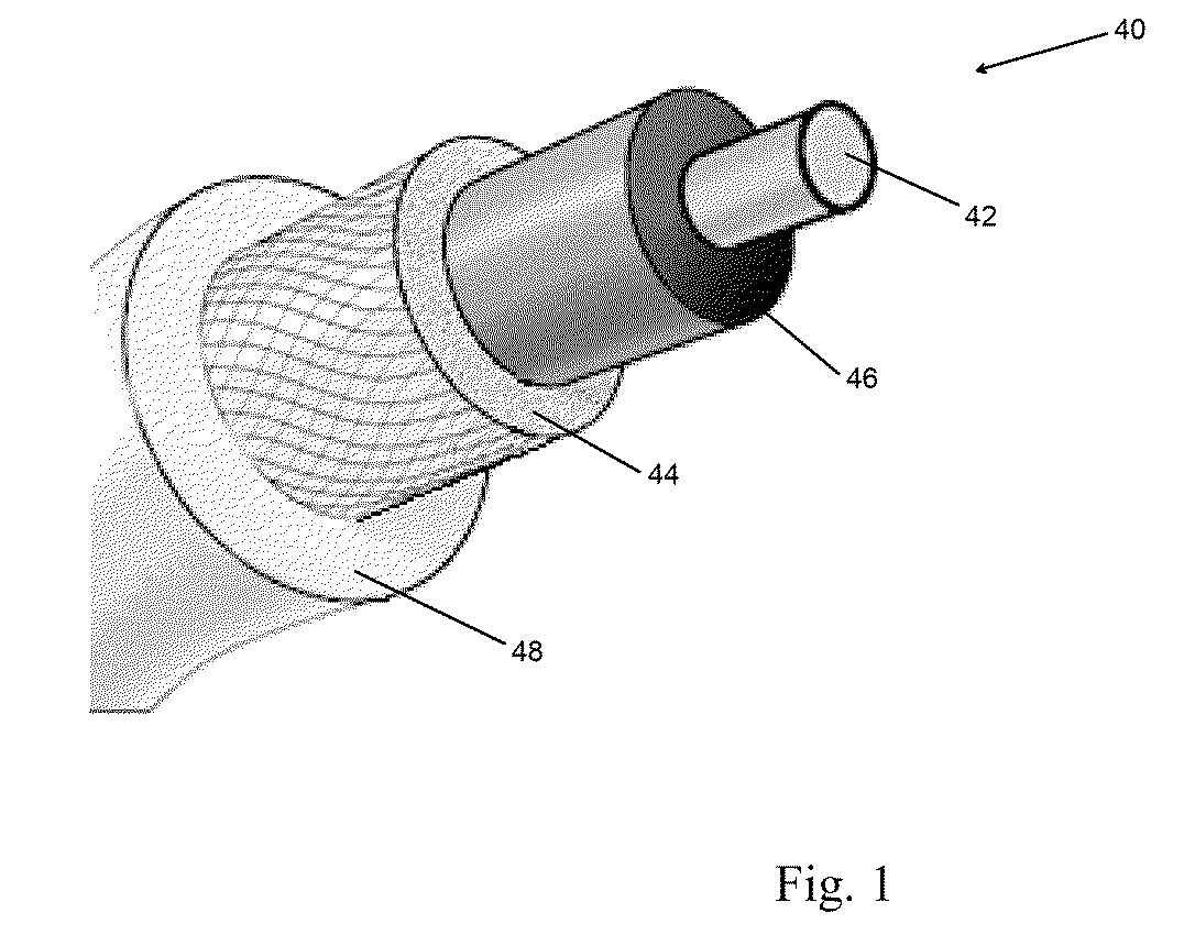
[0029]The present invention provides, in accordance with one embodiment, a cable. In an embodiment, the cable, as shown in FIG. 1, may include a conducting member 42 made from a nanostructure-based material. The cable may also include a shielding layer positioned about the conducting member 42. The cable may further include an insulation layer to improve conductivity and reduce resistivity of the cable. The cable may further include a coupling mechanism situated between the conducting member 42 and the shielding layer. The coupling mechanism may act to secure the shielding layer on the cable. The coupling mechanism further acts to maintain transmission of current along the conducting member 42.

[0030]Presently, there exist multiple processes and variations thereof for growing nanotubes, and forming sheets or cable structures made from these nanotubes. These include: (1) Chemical Vapor Deposition (CVD), a common process that can occur at near ambient or at high pressures, and at tempe...


PUM

PropertyMeasurementUnit
Temperatureaaaaaaaaaa
Percent by massaaaaaaaaaa

Abstract

A cable having a conducting member made from a nanostructure-based material, and a shielding layer made of nanostructure-based material. The shielding layer can be circumferentially situated about the conducting member so as to enhance conductivity along the conducting member. A coupling mechanism may be situated between the shielding layer and the conducting member so as to secure the shielding layer in its position on the conducting member. A method of making the cable is also disclosed.

Description

RELATED U.S. APPLICATION(S)[0001]The present application claims priority to U.S. Provisional Patent Application Ser. No. 61 / 051,249, filed May 7, 2008 which application is hereby incorporated by reference in its entirety.TECHNICAL FIELD[0002]The present invention relates to the formation of a cable, and more particularly, to a conducting member made from a nanostructure-based material and a shielding layer made from a material capable of providing substantially low resistance coupling.BACKGROUND ART[0003]Carbon nanotubes are known to have extraordinary tensile strength, including high strain to failure and relatively high tensile modulus. Carbon nanotubes may also be highly resistant to fatigue, radiation damage, and heat. To this end, the addition of carbon nanotubes to composite materials can increase tensile strength and stiffness of the composite materials.[0004]Within the last fifteen (15) years, as the properties of carbon nanotubes have been better understood, interests in ca...

Claims


Application Information

Patent Timeline
IPC IPC(8): H01B11/06B23P11/00
CPCH01B1/04Y10T428/30Y10T29/49826H01B13/0162H05K9/009H05K9/0098H01B11/06
Inventor MANN, JENNIFERLASHMORE, DAVID S.WHITE, BRIANANTOINETTE, PETER L.
Owner NANCOMP TECHNOLOGIES INC
Learn More