
Reservoir plunger head systems and methods

a plunger head and plunger technology, applied in the field of plunger head systems and methods, can solve the problem that the manual insertion of the needle into the user-patient can be somewhat traumatizing to the user-patien

Active Publication Date: 2009-12-31
MEDTRONIC MIMIMED INC
View PDF87 Cites 75 Cited by
  • Summary
  • Abstract
  • Description
  • Claims
  • Application Information

AI Technical Summary

Benefits of technology

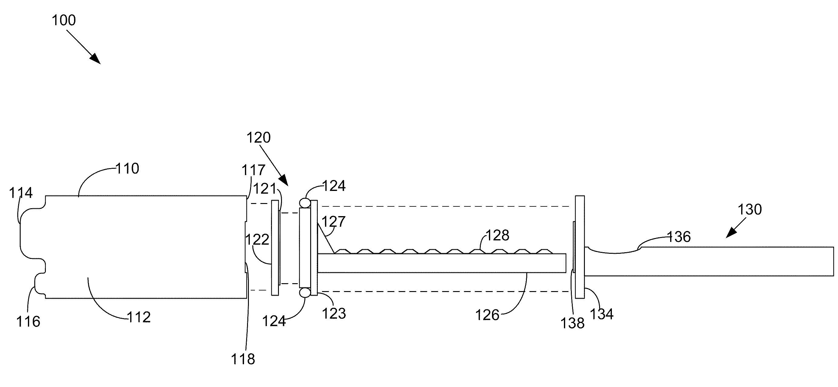
The present invention relates to a system for transferring fluidic media, which includes a plunger head moveable in an axial direction within a reservoir. The plunger head has a first portion in contact with the fluidic media, a second portion located opposite the interior volume of the reservoir, and a third portion between the first and second portions. The plunger head is made of a material that is compatible with the fluidic media and can be removably attached to the reservoir using a seal member. The system also includes a lubricant on the inner surface of the reservoir to facilitate the movement of the plunger head. The technical effects of the invention include improved compatibility with fluidic media, reduced friction, and improved performance of the system in transferring fluidic media.

Problems solved by technology

In contexts in which the hollow tubing is connected to the user-patient through a hollow needle that pierces the user-patient's skin, a manual insertion of the needle into the user-patient can be somewhat traumatic to the user-patient.

Method used


Image

  • Reservoir plunger head systems and methods
  • Reservoir plunger head systems and methods
  • Reservoir plunger head systems and methods

Examples


Embodiment Construction

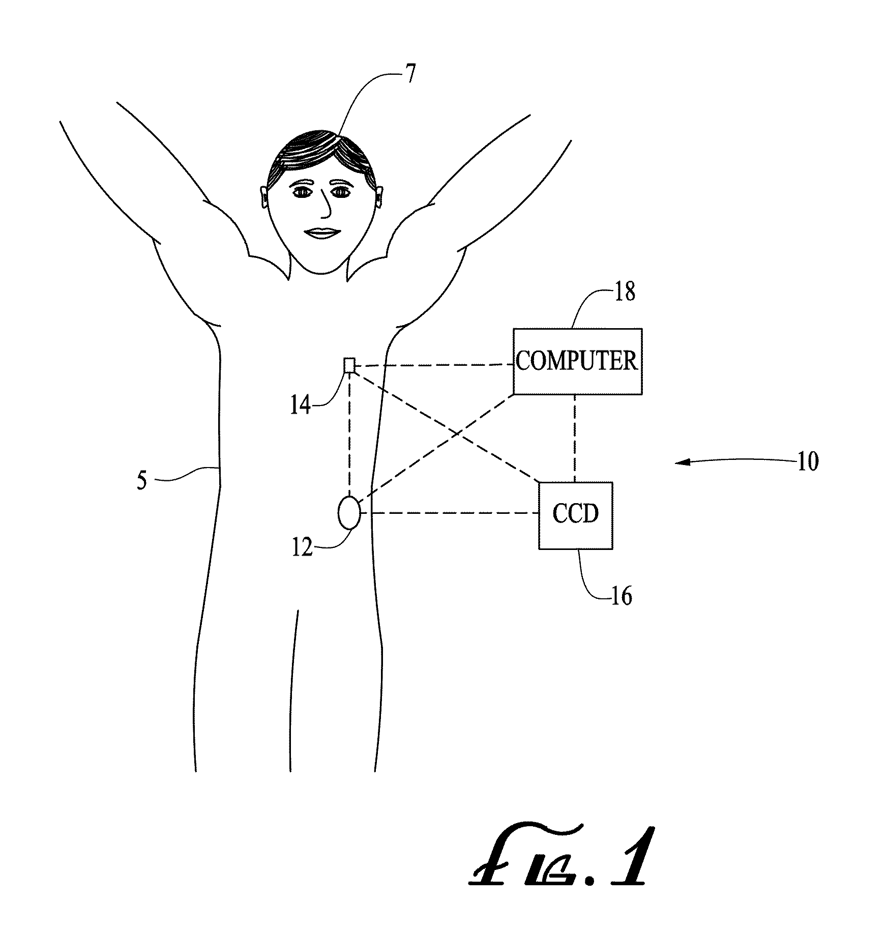
[0047]FIG. 1 illustrates a generalized representation of a system 10 in accordance with an embodiment of the present invention. The system 10 includes a delivery device 12. The system 10 may further include a sensing device 14, a command control device (CCD) 16, and a computer 18. In various embodiments, the delivery device 12 and the sensing device 14 may be secured at desired locations on the body 5 of a patient or user-patient 7. The locations at which the delivery device 12 and the sensing device 14 are secured to the body 5 of the user-patient 7 in FIG. 1 are provided only as representative, non-limiting, examples.

[0048]The system 10, the delivery device 12, the sensing device 14, the CCD 16, and computer 18 may be similar to those described in the following U.S. patent applications that were assigned to the assignee of the present invention, where each of following patent applications is incorporated herein by reference in its entirety: (i) U.S. patent application Ser. No. 11 / ...


PUM

PropertyMeasurementUnit
volumeaaaaaaaaaa
interior volumeaaaaaaaaaa
durableaaaaaaaaaa

Abstract

A plunger head moveable in an axial direction within a reservoir having an interior volume for containing fluidic media may have a first portion in contact with fluidic media when fluidic media is in the interior volume of the reservoir, the first portion comprising a first material compatible with fluidic media in the interior volume of the reservoir, a second portion located on an opposite side of the plunger head from the interior volume of the reservoir, the second portion connectable to a plunger arm, and a third portion located between the first portion and the second portion of the plunger head, at least one of the first portion, second portion, and the third portion is made of a material that comprises one of a cyclic olefin copolymer and a cyclic olefin polymer.

Description

CROSS-REFERENCE TO RELATED PATENT APPLICATIONS[0001]This application is a continuation-in-part of U.S. patent application Ser. No. 12 / 360,077, filed Jan. 26, 2009, which claim priority from Provisional Application Ser. No. 61 / 044,292, filed Apr. 11, 2008, both of which are herein incorporated by reference in their entirety. This application is also a continuation in part-of U.S. patent application Ser. No. 12 / 417,976, filed Apr. 3, 2009, which claim priority from Provisional Application Ser. No. 61 / 044,269, filed Apr. 11, 2008, both of which are incorporated herein by reference in their entirety.BACKGROUND[0002]1. Field of the Invention[0003]Embodiments of the present invention relate generally to systems and methods that include reservoirs for containing fluidic media and having movable plungers and, in specific embodiments, to infusion medium delivery systems and methods employing such reservoirs.[0004]2. Related Art[0005]According to modern medical techniques, certain chronic dis...

Claims


Application Information

Patent Timeline
Patent Type & Authority Applications(United States)
IPC IPC(8): A61M5/145B23P17/04B05D5/08
CPCA61B5/14532Y10T29/49826A61B5/4839A61M5/1413A61M5/14248A61M5/1452A61M5/1456A61M5/1723A61M5/31501A61M5/31513A61M2005/14268A61M2005/14573A61M2005/1726A61M2205/3561A61M2205/3569A61M2205/3592A61B5/14865
Inventor CHONG, COLIN A.LORENZEN, ERIC M.BIKOVSKY, RAFAELLUAN, TRUONG GIAIBRANYAN, ARSEN
Owner MEDTRONIC MIMIMED INC
Learn More