
Time code discrimination apparatus and wave clock

Active Publication Date: 2009-12-31
CASIO COMPUTER CO LTD
View PDF11 Cites 14 Cited by
  • Summary
  • Abstract
  • Description
  • Claims
  • Application Information

AI Technical Summary

Benefits of technology

[0009]It is, therefore, a main object of the preset invention to provide a time code discrimination apparatus and a wave clock that can accurately discriminate a reproduced time code to achieve accurate time correction even under poor radio wave conditions.

Problems solved by technology

If radio wave conditions are bad, a signal waveform of the received, time code may be collapsed, and it may be difficult to discriminate the time code.
Although the conventional technique for receiving and discriminating a time code can improve the sensitivity slightly, the conventional technique cannot improve the sensitivity to such a degree that accurate discrimination of the time code can be achieved under the condition that a signal is greatly attenuated and a noise ratio is increased, such as in a building.
Further, if the normal discrimination of the rime code is not performed, reception of the time code is performed several times. As a result, power consumption is increased.

Method used


Image

  • Time code discrimination apparatus and wave clock
  • Time code discrimination apparatus and wave clock
  • Time code discrimination apparatus and wave clock

Examples


first embodiment

[0030]FIG. 1 is a block diagram illustrating an internal configuration of a wave clock according to the preferred embodiments of the present invention.

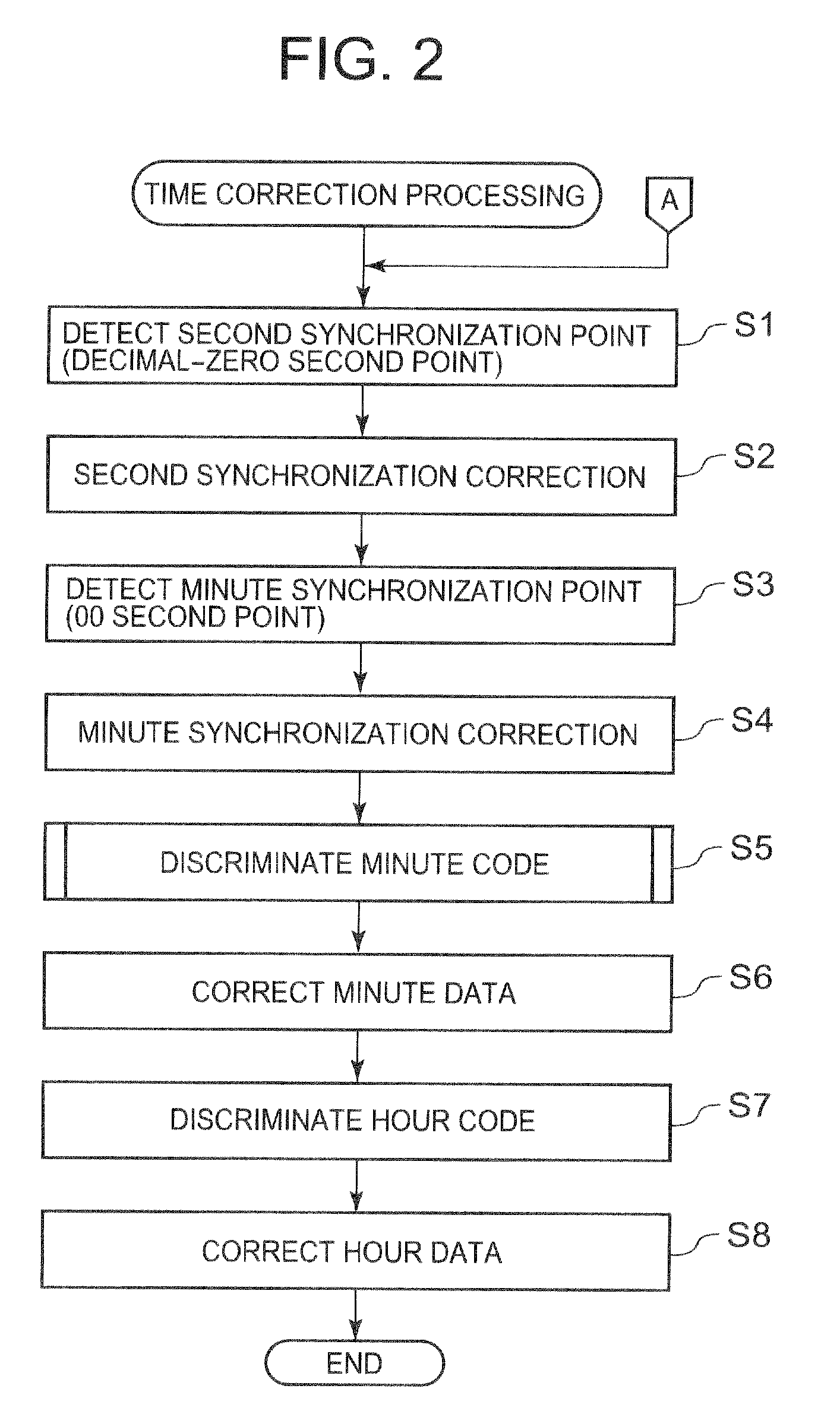
[0031]A wave clock 1 according to this embodiment is a body of a wristwatch, and has a function of receiving a standard radio wave and automatically correcting time using a time code. The wave clock 1 includes a display unit 11 that performs time display, a control circuit 10 that performs whole control of the apparatus, a storage unit 12 that stores control data or a control program, an input unit 13 that has a plurality of operation buttons, a timer circuit 15 that clocks time, an oscillation circuit 14 that supplies a predetermined frequency signal to the timer circuit 15, an antenna 19 that receives the standard radio wave, and a radio wave receiving IC 20 that receives the standard radio wave and demodulates the time code.

[0032]The control circuit 10 is composed of a microcomputer, and includes an AD converter that performs an AD...

second embodiment

[0091]A wave clock of a second embodiment is the same as that of the first embodiment except for a discrimination method of an one-minute digit code in the minute code discrimination processing (Step S5 of FIG. 2). Accordingly, only the configuration that is different from that of the first embodiment will be explained below.

[0092]FIG. 6 is a flowchart illustrating a first half of a minute data discrimination processing of the second embodiment. FIG. 7 is an illustration diagram of a comparison processing of one-minute digit codes according to the second embodiment. Specifically, FIG. 7-(a) shows timing data of the timer circuit 15, FIG. 7-(b) shows an one-minute digit code that is received, and reproduced, by the radio wave receiving IC 20, FIG. 7-(c) shows a plurality of sets of one-minute digit codes that are acquired and held by the control circuit 10, FIG. 7-(d) shows reference data indicating a transition pattern of an one-minute digit code, and FIG. 7-(e) shows a comparison p...


PUM


Abstract

Disclosed is a time code discrimination apparatus that discriminates a time code including one-minute digit and ten-minute digit codes. The time code discrimination apparatus includes: a first code acquiring section to acquire a plurality of sets of one-minute digit codes at a time interval in which the plurality of sets of one-minute digit codes are equal in value of one-minute digit; and a first code discrimination section to execute a process of reducing erroneous discrimination on the plurality of sets of one-minute digit codes acquired by the first code acquiring section, and to discriminate the one-minute digit codes.

Description

CROSS-REFERENCE TO RELATED APPLICATIONS[0001]This application is based upon and claims the benefit of priority from the prior Japanese Patent Application No. 2008-170317, filed on Jun. 30, 2008, the entire contents of which are incorporated herein by reference.BACKGROUND OF THE INVENTION[0002]1. Field of the Invention[0003]The present invention relates to a time code discrimination apparatus that discriminates a time code and a wave clock that receives a standard radio wave to discriminate a time code.[0004]2. Description of Related Art[0005]In recent years, wave clocks that receive a time code and automatically correct time of an internal clock have been used. The time code is transmitted by performing the amplitude modulation (II) on a carrier wave of 40 kHz or 60 kHz. If radio wave conditions are bad, a signal waveform of the received, time code may be collapsed, and it may be difficult to discriminate the time code.[0006]As techniques for receiving and discriminating the time co...

Claims


Application Information

Patent Timeline
IPC IPC(8): G04C11/02G04C11/00G04G5/00G04R20/00G04R20/12
CPCG04R20/10G04G5/002
Inventor SOMEYA, KAORU
Owner CASIO COMPUTER CO LTD
Learn More