
Inkjet recording apparatus and head maintenance method

a recording apparatus and head technology, applied in the direction of printing, other printing apparatus, etc., can solve the problems of limited ejection, inability to perform sufficient purging for each head, and limited head movement time, so as to prevent repeated scattering of recovered ink

Inactive Publication Date: 2009-12-31
FUJIFILM CORP
View PDF5 Cites 21 Cited by
  • Summary
  • Abstract
  • Description
  • Claims
  • Application Information

AI Technical Summary

Benefits of technology

[0010]The present invention has been contrived in view of these circumstances, an object thereof being to provide an inkjet recording apparatus based on a sheet-type pressure drum conveyance method and a head maintenance method which prevent scattering of ink into the periphery of a pressure drum where an inkjet head is provided, as well as carrying out desirable purging in order to ensure ejection stability of the inkjet head.
[0012]According to the present invention, an opening section corresponding to the ink ejection width of the inkjet head is provided in a non-holding region where a recording medium is not held on the circumferential surface of a pressure drum which holds and conveys a recording medium. Further, a suction flow channel connected to the opening section is formed in an integrated fashion with the opening section inside the pressure drum, and a composition is adopted whereby the opening section and the suction flow channel are suctioned at least in the droplet ejection region of the inkjet head. Therefore, it is possible to recover, inside the pressure drum, ink mist caused by droplet ejection by the inkjet head or ink that has been purged into the opening section, during image recording, as well as preventing repeated scattering of the recovered ink.

Problems solved by technology

However, the head movement time limits the extent to which the preliminary ejection operation time can be shortened, and this is particularly marked in apparatuses using a line type head in which a plurality of nozzles are arranged in the breadthways direction of the recording medium.
According to this method, it is not necessary to move the head each time a preliminary ejection operation is carried out, but if preliminary ejection is carried out onto the recording medium, then the position where preliminary ejection can be performed is limited to a narrow region, such as the margins, and sufficient purging cannot be performed for each of the heads.
Furthermore, if forming images on a recording medium of narrower width than the ejection width of the line type head, it is difficult to perform preliminary ejection throughout the whole width of the head.
However, in the liquid spray apparatus described in Japanese Patent Application Publication No. 2006-159556, a composition is adopted in which paper is suctioned and conveyed while suctioning the ink ejected by preliminary ejection, and consequently there is a large amount of sliding between the conveyance belt and the liquid receiving section, and operational errors such as slippage, and problems such as stretching of the conveyance belt, or deformation or rupture of the preliminary ejection holes, or the like, are liable to occur.
Furthermore, if a plurality of heads are provided so as to correspond to a plurality of colors, then the liquid receiving section needs the sufficient length in the conveyance direction and the apparatus is liable to become larger in size.
Furthermore, it is difficult to recover ink (ink mist) which has been propelled into the air.

Method used


Image

  • Inkjet recording apparatus and head maintenance method
  • Inkjet recording apparatus and head maintenance method
  • Inkjet recording apparatus and head maintenance method

Examples


first example

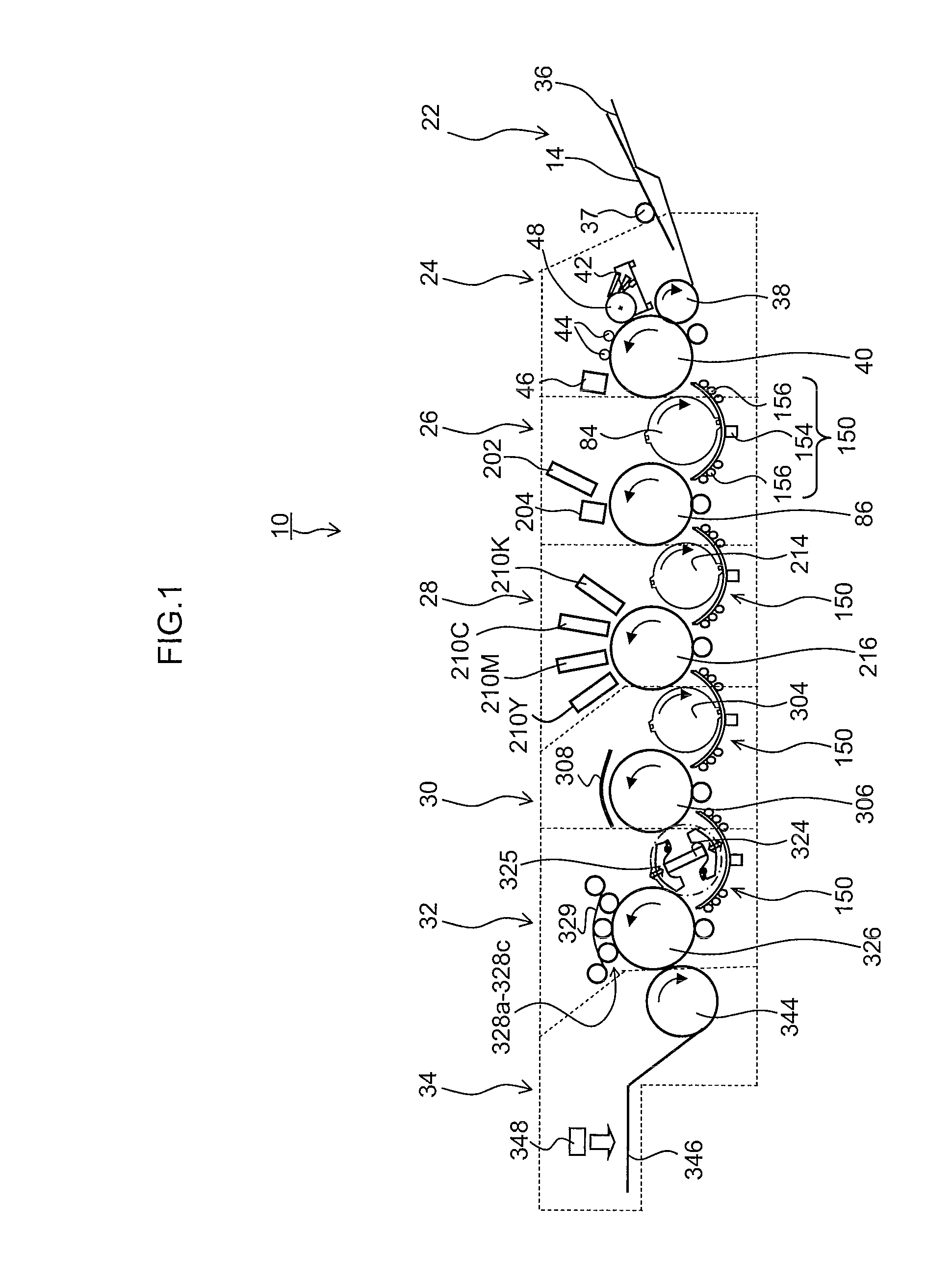
[0128]FIG. 14 is a cross-sectional diagram illustrating an example of the structure of the pressure drum 216 (first example). As illustrated in FIG. 14, the pressure drum 216 is provided at a position opposing the ink ejection surfaces of the inkjet heads 210K, 210C, 210M and 210Y, and holds and rotates the recording medium 14 on the circumferential surface thereof, thus conveying the recording medium 14 along the circumferential surface.

[0129]Grippers 500 and 502 which hold the leading edge portion of a recording medium 14 are provided respectively at opposing positions on either side of the rotational axis of the circumferential surface of the pressure drum 216, and furthermore, a plurality of suctioning holes which apply a suctioning pressure to the recording medium 14 (not illustrated in FIG. 14; indicated by reference numeral 508 in FIG. 15) are provided respectively in two recording medium holding positions (not illustrated in FIG. 14; indicated by reference numeral 507 in FIG...

second example

[0141]Next, a further example of the pressure drum described above (second example) is explained. FIG. 16 is a cross-sectional diagram illustrating the structure of a pressure drum 216′ relating to a second example. In FIG. 16, parts which are the same as or similar to the drawings described previously are labeled with the same reference numerals and further explanation thereof is omitted here.

[0142]As illustrated in FIG. 16, opening sections 504A and 504B are provided respectively in two recording medium holding sections provided in the circumferential surface of the pressure drum 216′, and purging from the heads 210K, 210C, 210M and 210Y can be carried out two times in one revolution (once during each half revolution of the pressure drum 216′), following the respective recording medium holding positions (indicated by reference numeral 507 in FIG. 17).

[0143]Furthermore, a suction guide 510 having a length corresponding to the ink ejection width of the heads 210K, 210C, 210M and 210...

third example

[0153]Next, yet a further example of the pressure drum described above (third example) is explained. FIG. 18A is a cross-sectional diagram of the pressure drum 216″ relating to this third example. In the pressure drum 216″ illustrated in FIG. 18A, the suction units 540 are accommodated inside the opening sections 504A and 504B. Furthermore, by moving the unit sliding axle 542 which also serves as the suction guide, it is possible to cause the suction unit 540 to make tight contact with the region corresponding to the ink ejection region of the ink ejection surface of the heads 210K, 210C, 210M and 210Y.

[0154]The suction units 540 are provided respectively in the plurality of opening sections 504A and 504B which are provided in the axial direction of the pressure drum 216″. If each of the heads 210K, 210C, 210M and 210Y is a line head having a length corresponding to the full width of the recording medium 14, then if a plurality of suction units 540 which are each shorter than the fu...


PUM


Abstract

An inkjet recording apparatus has: an inkjet head which has an ink ejection surface and ejects droplets of an ink from the ink ejection surface onto a recording medium; a pressure drum which is disposed in a position opposing the ink ejection surface of the inkjet head, has a round cylindrical circumferential surface in which a recording medium holding position and a non-holding position are provided, an opening section corresponding to an ink ejection width of the inkjet head in the non-holding position where the recording medium is not held, a suction flow channel that is connected to the opening section and provided integrally with the opening section inside the pressure drum, and holds and rotates the recording medium at the recording medium holding position in such a manner that the recording medium is conveyed in a circumferential direction of the pressure drum; and a suctioning device which suctions the opening section and the suction flow channel at least in a droplet ejection region where the droplets of the ink are ejected from the inkjet head.

Description

BACKGROUND OF THE INVENTION[0001]1. Field of the Invention[0002]The present invention relates to an inkjet recording apparatus and a head maintenance method, and more particularly to maintenance technology for an inkjet head.[0003]2. Description of the Related Art[0004]An inkjet recording apparatus which records color images by ejecting color inks onto a recording medium from a plurality of nozzles provided in an inkjet head maintains uniform image quality by carrying out a preliminary ejection operation at fixed intervals from the inkjet heads of the respective colors. A general inkjet recording apparatus is composed in such a manner that preliminary ejection (purging) is carried out by moving the head to a special preliminary ejection position or capping position. However, the head movement time limits the extent to which the preliminary ejection operation time can be shortened, and this is particularly marked in apparatuses using a line type head in which a plurality of nozzles a...

Claims


Application Information

Patent Timeline
Patent Type & Authority Applications(United States)
IPC IPC(8): B41J2/165
CPCB41J13/223B41J2/16585
Inventor HORI, HISAMITSU
Owner FUJIFILM CORP
Learn More