Inkjet recording apparatus and head maintenance method
a recording apparatus and head technology, applied in the direction of printing, other printing apparatus, etc., can solve the problems of limited ejection, inability to perform sufficient purging for each head, and limited head movement time, so as to prevent repeated scattering of recovered ink
- Summary
- Abstract
- Description
- Claims
- Application Information
AI Technical Summary
Benefits of technology
Problems solved by technology
Method used
Image
Examples
first example
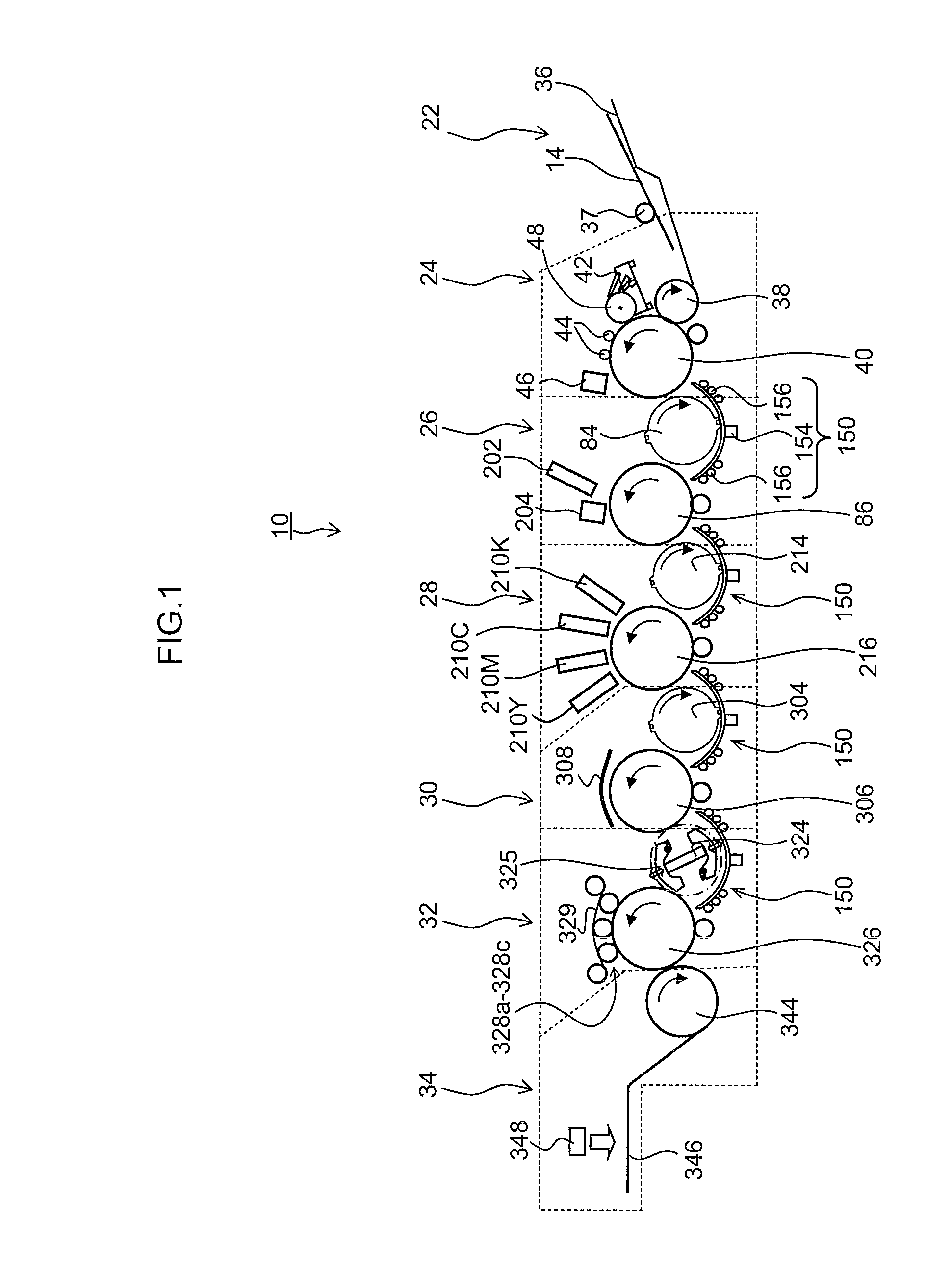
[0128]FIG. 14 is a cross-sectional diagram illustrating an example of the structure of the pressure drum 216 (first example). As illustrated in FIG. 14, the pressure drum 216 is provided at a position opposing the ink ejection surfaces of the inkjet heads 210K, 210C, 210M and 210Y, and holds and rotates the recording medium 14 on the circumferential surface thereof, thus conveying the recording medium 14 along the circumferential surface.
[0129]Grippers 500 and 502 which hold the leading edge portion of a recording medium 14 are provided respectively at opposing positions on either side of the rotational axis of the circumferential surface of the pressure drum 216, and furthermore, a plurality of suctioning holes which apply a suctioning pressure to the recording medium 14 (not illustrated in FIG. 14; indicated by reference numeral 508 in FIG. 15) are provided respectively in two recording medium holding positions (not illustrated in FIG. 14; indicated by reference numeral 507 in FIG...
second example
[0141]Next, a further example of the pressure drum described above (second example) is explained. FIG. 16 is a cross-sectional diagram illustrating the structure of a pressure drum 216′ relating to a second example. In FIG. 16, parts which are the same as or similar to the drawings described previously are labeled with the same reference numerals and further explanation thereof is omitted here.
[0142]As illustrated in FIG. 16, opening sections 504A and 504B are provided respectively in two recording medium holding sections provided in the circumferential surface of the pressure drum 216′, and purging from the heads 210K, 210C, 210M and 210Y can be carried out two times in one revolution (once during each half revolution of the pressure drum 216′), following the respective recording medium holding positions (indicated by reference numeral 507 in FIG. 17).
[0143]Furthermore, a suction guide 510 having a length corresponding to the ink ejection width of the heads 210K, 210C, 210M and 210...
third example
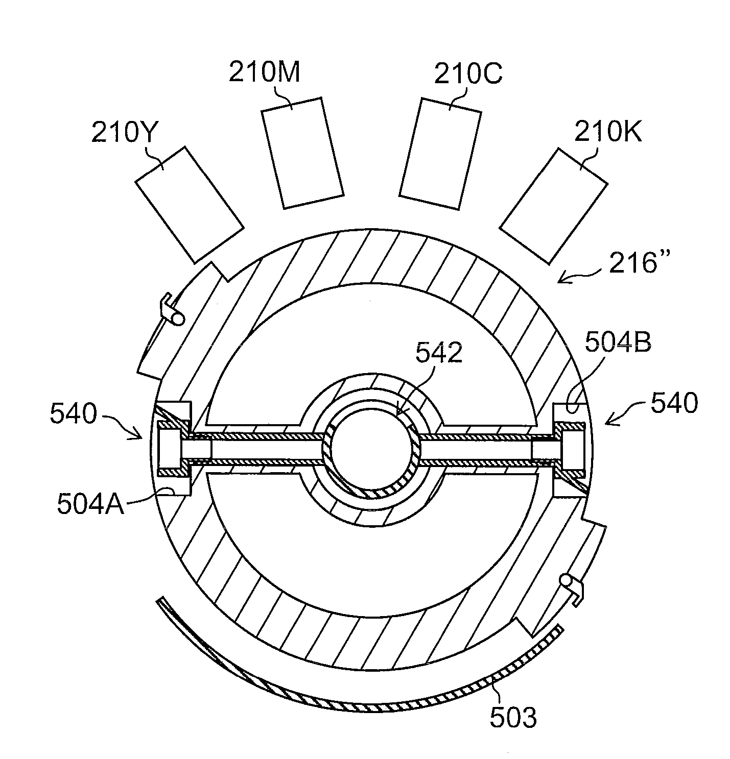
[0153]Next, yet a further example of the pressure drum described above (third example) is explained. FIG. 18A is a cross-sectional diagram of the pressure drum 216″ relating to this third example. In the pressure drum 216″ illustrated in FIG. 18A, the suction units 540 are accommodated inside the opening sections 504A and 504B. Furthermore, by moving the unit sliding axle 542 which also serves as the suction guide, it is possible to cause the suction unit 540 to make tight contact with the region corresponding to the ink ejection region of the ink ejection surface of the heads 210K, 210C, 210M and 210Y.
[0154]The suction units 540 are provided respectively in the plurality of opening sections 504A and 504B which are provided in the axial direction of the pressure drum 216″. If each of the heads 210K, 210C, 210M and 210Y is a line head having a length corresponding to the full width of the recording medium 14, then if a plurality of suction units 540 which are each shorter than the fu...
PUM
 Abstract
Description
Claims
Application Information
 - R&D
- Intellectual Property
- Life Sciences
- Materials
- Tech Scout
- Unparalleled Data Quality
- Higher Quality Content
- 60% Fewer Hallucinations
Browse by: Latest US Patents, China's latest patents, Technical Efficacy Thesaurus, Application Domain, Technology Topic, Popular Technical Reports.
© 2025 PatSnap. All rights reserved.Legal|Privacy policy|Modern Slavery Act Transparency Statement|Sitemap|About US| Contact US: help@patsnap.com


