
Push-Position Indicator for Appliance Door

a technology for positioning indicators and appliance doors, which is applied in the field of push-position indicators for appliance doors, can solve problems such as confusion on the part of users regarding push-position latch mechanisms, and the limited use of push-position latch mechanisms

Active Publication Date: 2009-12-31
ELECTROLUX HOME PROD CORP NV
View PDF6 Cites 20 Cited by
  • Summary
  • Abstract
  • Description
  • Claims
  • Application Information

AI Technical Summary

Benefits of technology

[0018]According to a further aspect of the present invention, a method for changing the mount of an appliance door to an appliance cabinet is provided. The appliance door has a hinge structure, a latch structure, first and second cut-outs configured to interchangeably receive a push-position indicator member. The method includes interchanging the mount location of the latch structure and the hinge structure, and interchanging the mount location of the push-position indicator member from one to the other of the first and second cut-outs, so as to place the indicator member in closer proximity to the latch structure than the hinge structure.

Problems solved by technology

Limited use has been made of push-push latch mechanisms in door assemblies for laundry appliances.
This may lead, however, to confusion on the part of users regarding the manner in which the door is to be opened, especially if the hinge and latch locations of the door are subject to change, such as is the case with the door assembly described in aforementioned U.S. application Ser. No. 11 / 944,032.
However, such interchangeability can exacerbate the potential for user confusion if the appliance door employs a push-push mechanism and is provided with a sleek, unencumbered exterior surface.
A press on the wrong side (e.g., the hinge side) of the door may be ineffective to open the door or require excessive force.
A simple mark, such as a decal, embossment or adhesively applied button or the like could be used, except that such an arrangement may detract from the aesthetics of the appliance and may not have the durability to last, especially given the potential for exposure to chemicals that may be used in conjunction with a laundry washer.

Method used


Image

  • Push-Position Indicator for Appliance Door
  • Push-Position Indicator for Appliance Door
  • Push-Position Indicator for Appliance Door

Examples


Embodiment Construction

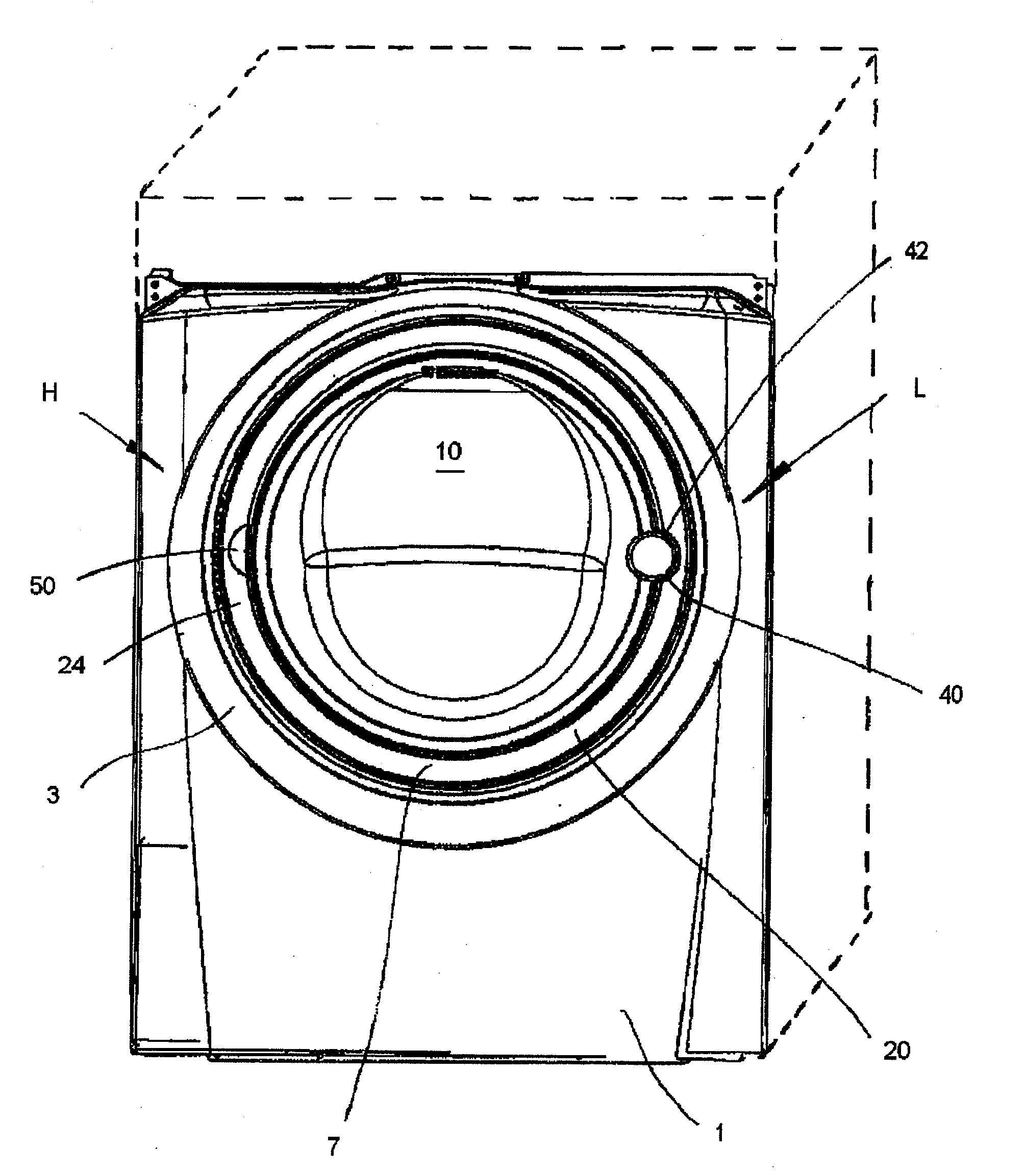
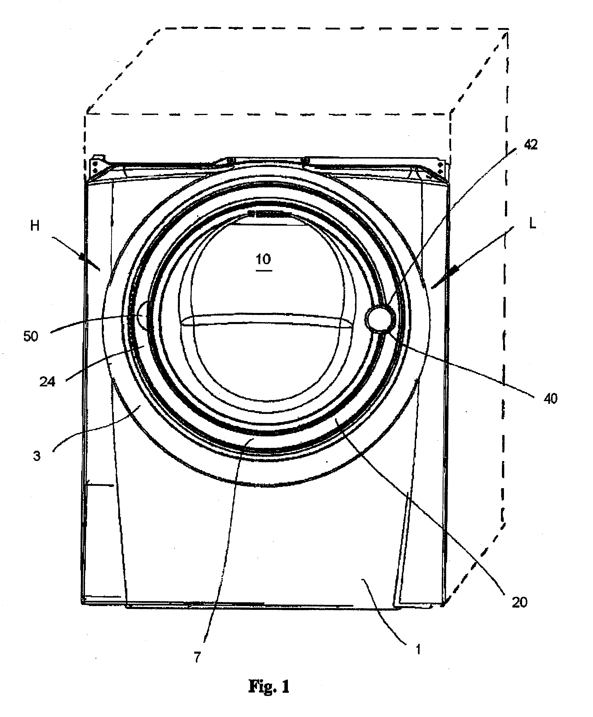
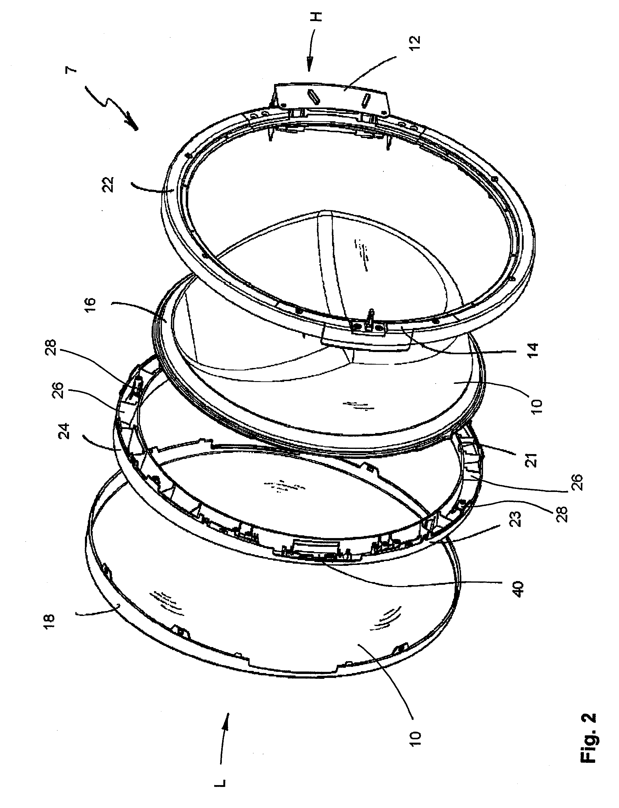
[0031]Referring to FIG. 1, a front-load laundry appliance includes a front panel or bulkhead 1 to which is mounted a hinged laundry appliance door 7 that may be swung open to provide front-load access to a rotatable drum-type chamber, through a porthole 3. As illustrated in FIG. 1, the laundry appliance may be a front-load washing machine. Alternatively, the laundry appliance may be a dryer. Laundry appliance door 7, illustratively provided in the form of a circular porthole cover, includes a central see-through window portion 10 and a surrounding circumferential door frame assembly 20. Laundry appliance door 7 has a hinge side H and a latch side L. As best shown in FIG. 2, hinge structure 12 is located on hinge side H and latch structure 14 is located on latch side L of door 7.

[0032]Referring back to FIG. 1, laundry appliance door 7 is shown attached to appliance front panel 1 in a first hinge / latch configuration, wherein the hinge side H of laundry appliance door 7 is hingedly att...


PUM


Abstract

A push-push appliance door, e.g., for a front-load automatic laundry washer, includes a peripheral frame having a first cut-out configured to receive a push-position indicator member that designates a push-position for opening the door. The frame may include a second cut-out located on an opposite side of the frame from the first cut-out. The door may further include a cut-out filler piece. The first and second cut-outs may be configured to interchangeably and interlockingly receive the indicator member and the cut-out filler piece, to thereby allow the indicator member to be properly positioned in relation to a selection of a hinge / latch location.

Description

FIELD OF THE INVENTION[0001]The present invention relates generally to appliance doors, and particularly to features facilitating user operation (i.e., opening and closing) of appliance doors.BACKGROUND[0002]In a modern trend, laundry appliances are taking on a more visually prominent role in the home, serving as statement pieces reflecting individual style. Consequently, the aesthetics of the laundry appliance is an important factor in the design of a laundry appliance and its components. Relatedly, greater emphasis is being placed on the “look and feel” of the operation features of laundry appliances. The access door of the laundry appliance is just such a feature, which is also very visually prominent.[0003]Co-pending commonly owned U.S. application Ser. No. 11 / 944,032, filed Nov. 21, 2007, and titled “Laundry Appliance Over-Molded Metal Porthole Door Frame,” incorporated by reference in its entirety herein, discloses a multi-component laundry appliance door assembly suitable for...

Claims


Application Information

Patent Timeline
Patent Type & Authority Applications(United States)
IPC IPC(8): D06F39/14
CPCD06F39/14
Inventor HILL, CHRIS H.NORMAN, DOUGLAS C.SCHOTT, JASONNADOLNY, REYNALDORIPLEY, BRIAN D.
Owner ELECTROLUX HOME PROD CORP NV
Learn More