
Synthetic rope socket

a technology of synthetic rope and socket, which is applied in the direction of snap fasteners, buckles, mechanical apparatus, etc., can solve the problems of requiring cumbersome connections, requiring specialized fabrication, and long installation times, and achieve the effect of preventing damag

Inactive Publication Date: 2009-12-31
NAQUIN ANDREW +3
View PDF21 Cites 9 Cited by
  • Summary
  • Abstract
  • Description
  • Claims
  • Application Information

AI Technical Summary

Benefits of technology

[0009]The apparatus of the present invention includes a synthetic eye socket used to terminate the ends of synthetic rope lines offering protection, strength, and ease of connections.
[0010]The apparatus also allows the field installation of synthetic ropes already possessing an eye due to the incorporation of a removable thimble that facilitates both the addition of an existing line or the separation of an installed line without separating the rope eye. This feature offers both increased safety and time savings while offshore in suddenly changing and severe environmental conditions.
[0011]The apparatus also allows for the interconnection of synthetic ropes without the use of other intermediate hardware. The apparatus also has built in provisions to secure the synthetic rope eyes to prevent fouling during operations.

Problems solved by technology

On the production side of the equation, if an oil discovery is found in deepwater, a floating production unit is needed and faces the same design challenges as the drilling rigs.
While the synthetic ropes have been undergoing significant changes in design, they have also been requiring cumbersome connections requiring specialized fabrication, longer installation times, and significantly longer man hours.
Securing a synthetic line on deck for connection or disconnection on many occasions requires elaborate braiding of smaller lines around the large line to prevent slipping and falling to the sea floor, a very time-consuming process.
Today, installation crews have to remove all connectors, such as shackles and pins, before loading the winches, because all of these have sharp edges and can destroy the integrity of the synthetic mooring lines, another time-consuming process.

Method used


Image

  • Synthetic rope socket
  • Synthetic rope socket
  • Synthetic rope socket

Examples


Embodiment Construction

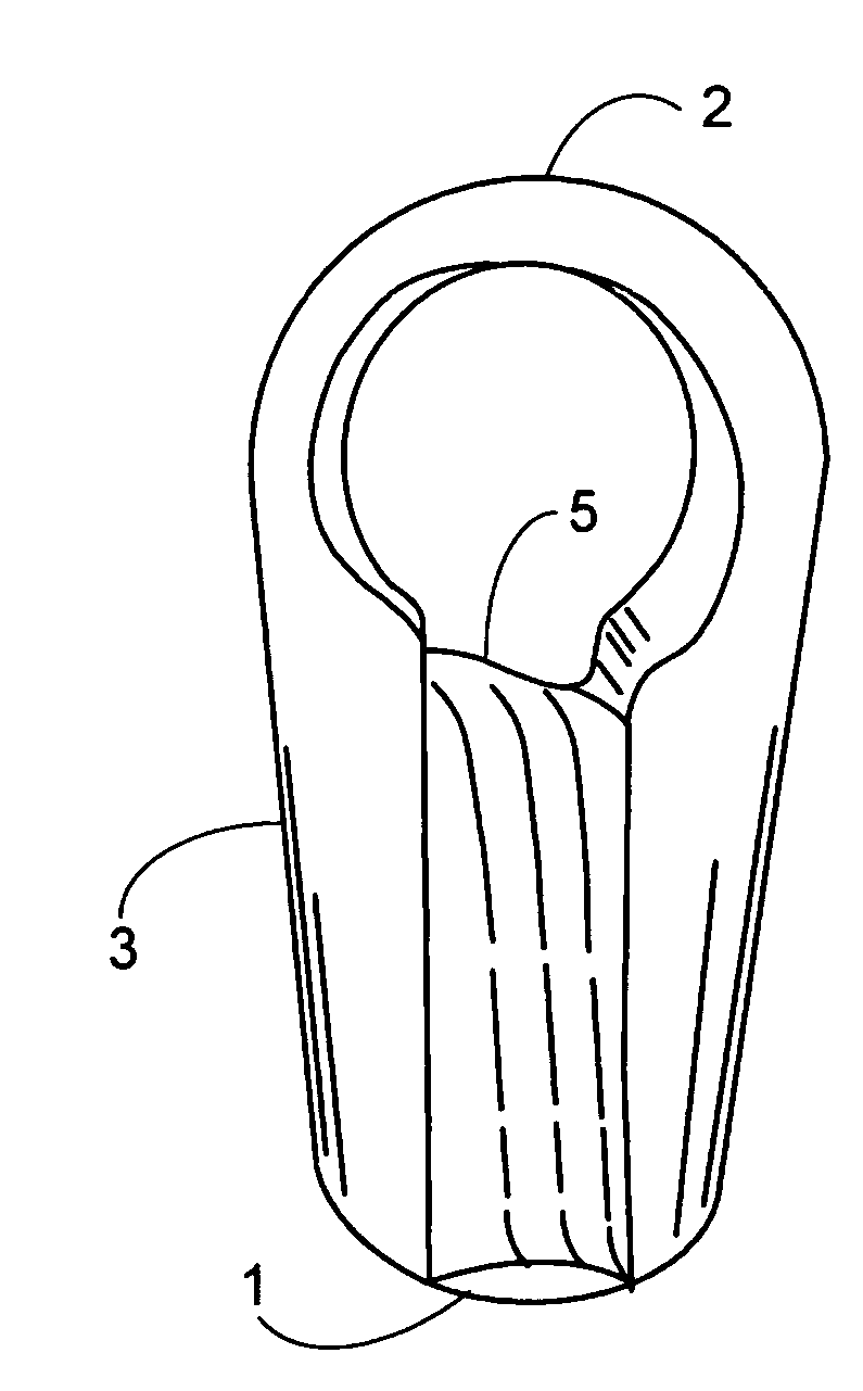
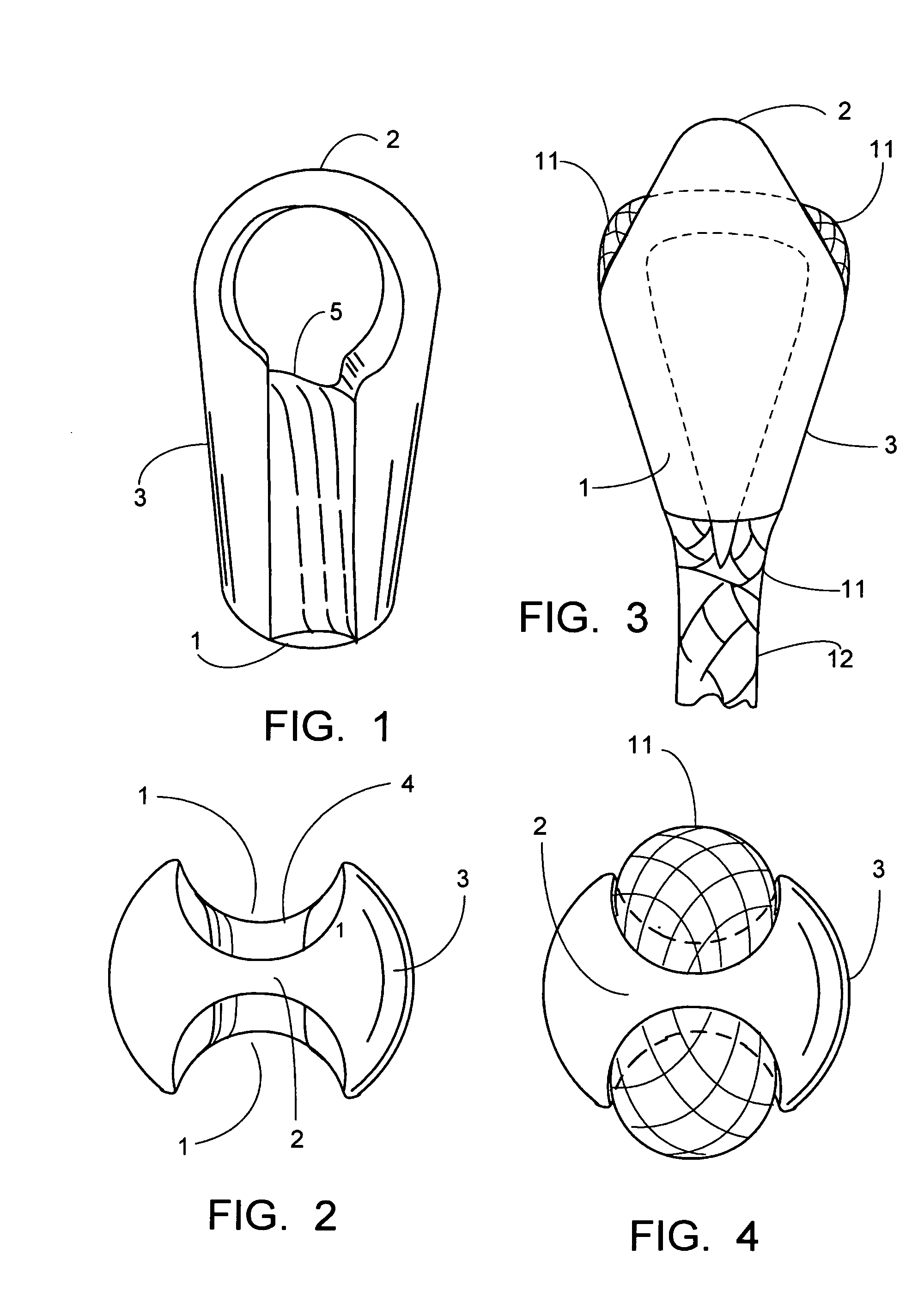
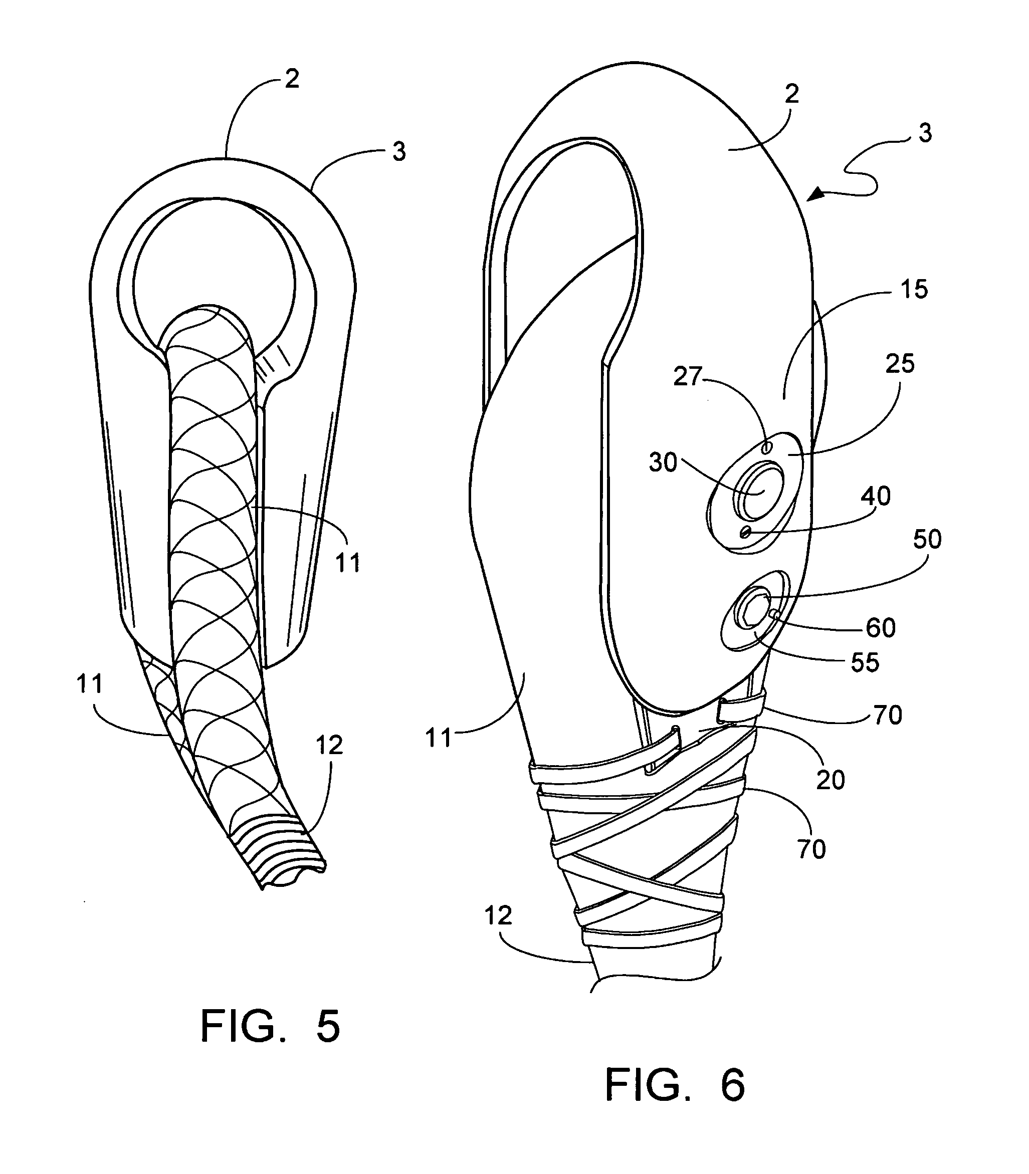
[0023]FIG. 1 is a perspective view showing the profile of a synthetic eye socket 3. The preferably solid cast or forged socket will preferably have a groove 1 running from bottom to top on both sides as shown in FIG. 1. Preferably, synthetic rope 12 containing a synthetic rope eye 11 will enter and exit the synthetic eye socket 3 with a splice performed just below the synthetic eye socket 3. FIG. 1 shows the bale 2 that is the attaching point for connections. These connections can be various other items in the system, such as anchor chain, wire rope, another synthetic line with socket, etc. The bale 2 will allow the use of connecting links, much like the steel wire rope sockets that have been in use for years. These connecting links can be received in the eye 4 of the bale 2. For this reason the commonly used connecting links will now work with synthetic rope lines reducing installation times and cost. The figures show the conical shape of the synthetic eye socket 3, which preferabl...


PUM


Abstract

A device for termination of synthetic rope, with an eye socket substantially free of sharp edges, a bale at the top of the eye socket with an eye for attachment of connecting links, a groove for receiving synthetic rope. In addition, the device includes a bale with extended sides at the top of the eye socket, a thimble within a synthetic rope eye contained within the extended sides and restrained from translation by pin. A shroud is also provided for protection at the bottom of the eye socket at the synthetic rope splice. The device is intended to aid in the efficient and safe connections to other objects such as other synthetic mooring lines, steel wire rope, and anchor chains.

Description

[0001]This application claims priority from U.S. Provisional application Ser. No. 61 / 077,119 (“the '119 application”) filed Jun. 30, 2008, and U.S. Provisional application Ser. No. 61 / 203,134 (“the '134 application”). The '119 and '134 applications are incorporated herein by reference.BACKGROUND OF THE INVENTION[0002]1. Field of the Invention[0003]The present invention relates to a device for terminating synthetic mooring line ends currently used in the mooring of permanent and temporary offshore drilling and production facilities. More particularly, the present invention relates to a grooved, preferably metal socket used on the ends of synthetic mooring lines which enhances the protection of the mooring line, decreases installation time and costs, and preferably utilizes industry standard wire rope or chain connectors.[0004]2. General Background of the Invention[0005]The oilfield, due to increased pressures from the marketplace, has steadily looked to drilling in deeper waters. Whi...

Claims


Application Information

Patent Timeline
Patent Type & Authority Applications(United States)
IPC IPC(8): F16G11/00
CPCY10T403/4336Y10T24/3916F16G11/00Y10T24/39Y10T24/3991F16G11/02F16G11/14
Inventor NAQUIN, ANDREWHAUN, RICHARD D.HALL, RICHARD E.KAZUNAS, PETER L.
Owner NAQUIN ANDREW
Learn More