
Model based optimization of multiple power generating units

a technology of model optimization and power generating units, applied in the direction of adaptive control, program control, instruments, etc., can solve the problem that the prior art does not describe a coordinated approach to optimizing multiple components

Active Publication Date: 2009-12-24
GE DIGITAL HLDG LLC
View PDF26 Cites 48 Cited by
  • Summary
  • Abstract
  • Description
  • Claims
  • Application Information

AI Technical Summary

Benefits of technology

This approach enables comprehensive optimization of power generating units, effectively reducing NOx, SOx, mercury, and particulate matter emissions while minimizing costs and maximizing efficiency by coordinating the operation of multiple components within and across units.

Problems solved by technology

However, the prior art does not describe a coordinated approach to optimization of multiple components, within a single power generating unit or multiple power generating units, to achieve multi-pollutant reductions (NOx, SOx, Mercury, CO and particulate matter), minimize costs, and maximize efficiency.

Method used


Image

  • Model based optimization of multiple power generating units
  • Model based optimization of multiple power generating units
  • Model based optimization of multiple power generating units

Examples


Embodiment Construction

[0049]It should be understood that the various systems described in the illustrated embodiments of the present invention may take the form of computer hardware, computer software, or combinations thereof. The computer hardware may take the form of a conventional computer system including a processor, data storage devices, input devices (e.g., keyboard, mouse, touch screen and the like), and output devices (e.g., display devices such as monitors and printers), or be embodied as part of another computer system.

[0050]Furthermore, the specific inputs and outputs of each model disclosed herein are shown solely for the purpose of illustrated an embodiment of the present invention. In this regard, it is contemplated that the specific model inputs and outputs may vary according to the requirements of the model and the desired predicted values that are being determined by the model.

[0051]The present invention is described herein with reference to power generating units for the generation of ...


PUM


Abstract

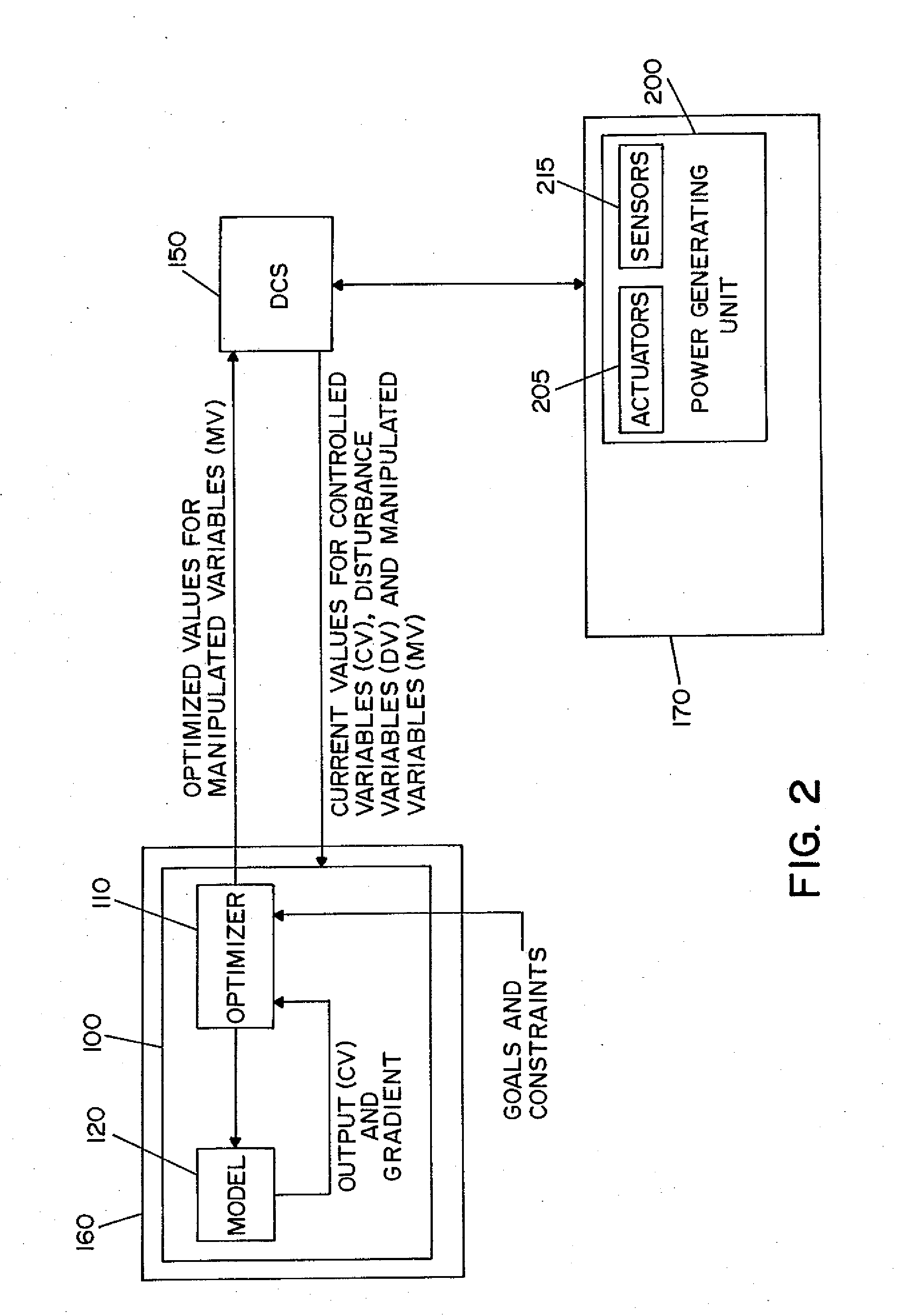
A method and apparatus for optimizing the operation of a single or multiple power generating units using advanced optimization, modeling, and control techniques. In one embodiment, a plurality of component optimization systems for optimizing power generating unit components are sequentially coordinated to allow optimized values determined by a first component optimization system to be fed forward for use as an input value to a subsequent component optimization system. A unit optimization system may be provided to determine goals and constraints for the plurality of component optimization systems in accordance with economic data. In one embodiment of the invention, a multi-unit optimization system is provided to determine goals and constraints for component optimization systems of different power generating units. Both steady state and dynamic models are used for optimization.

Description

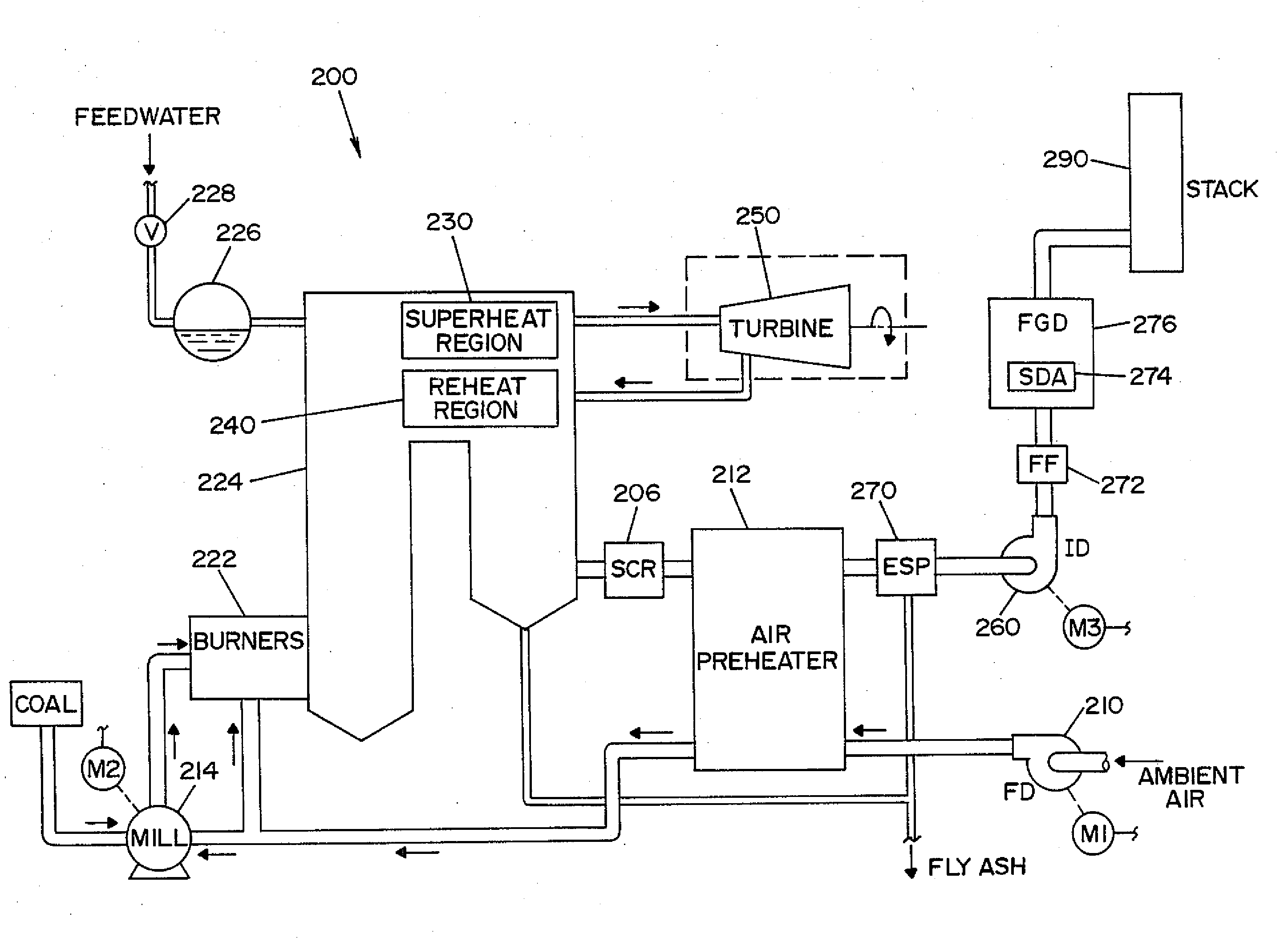
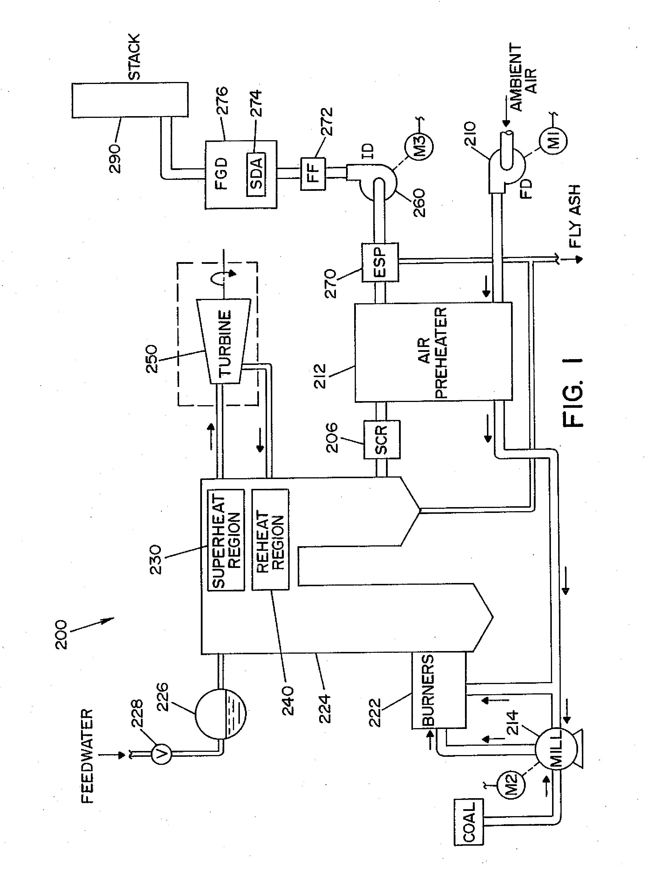
RELATED APPLICATIONS[0001]This application is a divisional of U.S. application Ser. No. 11 / 314,214, filed Dec. 21, 2005, and is hereby fully incorporated herein by reference.FIELD OF THE INVENTION[0002]The present invention relates generally to the operation of a single or multiple power generating units, and more particularly to a method and apparatus for optimizing the operation of a single or multiple power generating units using advanced optimization, modeling, and control techniques.BACKGROUND OF THE INVENTION[0003]In a conventional fossil fuel-fired (e.g., coal-fired) power generating unit, a fossil fuel / air mixture is ignited in a boiler. Large volumes of water are pumped through tubes inside the boiler, and the intense heat from the burning fuel turns the water in the boiler tubes into high-pressure steam. In an electric power generating application, the high-pressure steam from the boiler passes into a turbine comprised of a plurality of turbine blades. Once the steam hits ...

Claims


Application Information

Patent Timeline
Patent Type & Authority Applications(United States)
IPC IPC(8): G05B13/04G06F1/28G05B13/02
CPCF23N2023/40F23N2023/44H02J3/38Y02E60/76Y04S10/545Y04S40/22Y02E40/76H02J2003/007F23N2223/40F23N2223/44G05B19/0426G05B2219/2639H02J2203/20Y02E40/70Y02E60/00Y04S10/50Y04S40/20
Inventor PICHE, STEPHEN
Owner GE DIGITAL HLDG LLC
Learn More