
Variably Transmittive, Electronically-Controlled Eyewear

Active Publication Date: 2009-12-24
NASA
View PDF11 Cites 7 Cited by
  • Summary
  • Abstract
  • Description
  • Claims
  • Application Information

AI Technical Summary

Benefits of technology

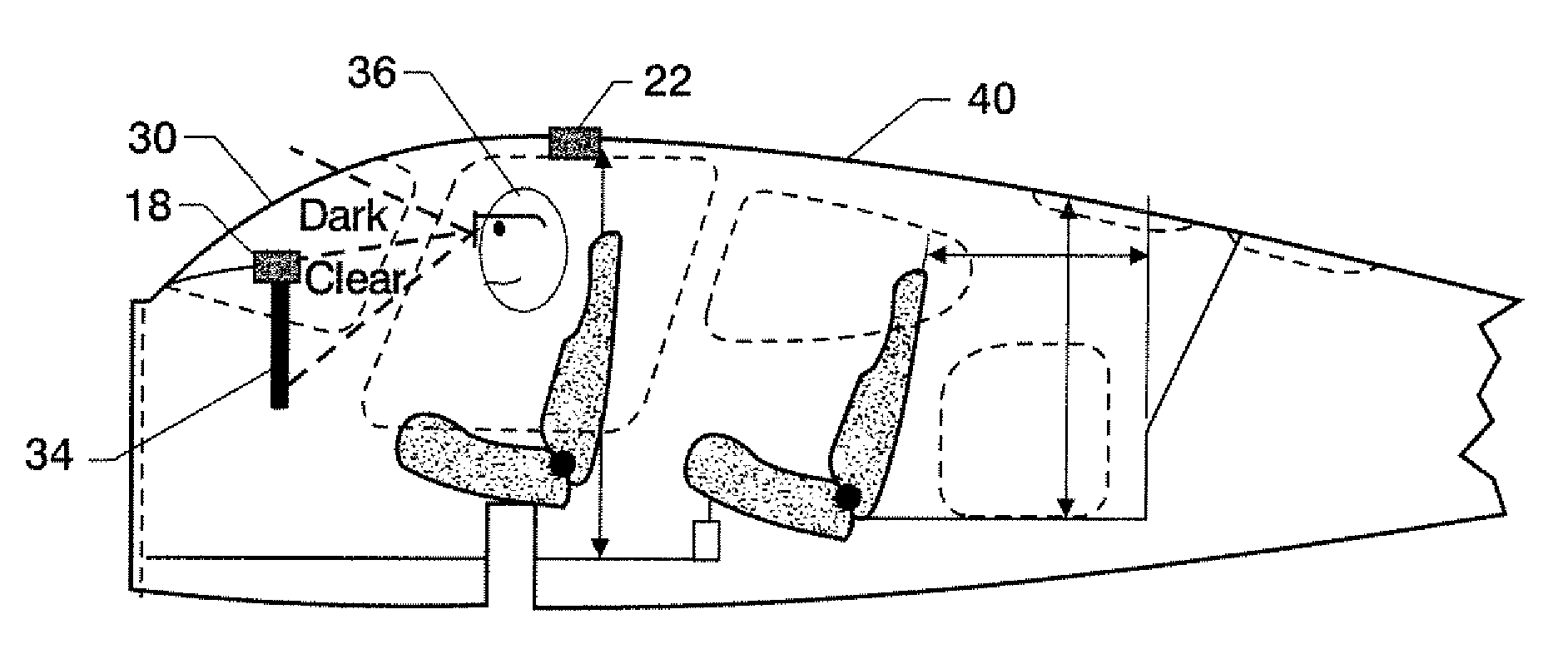
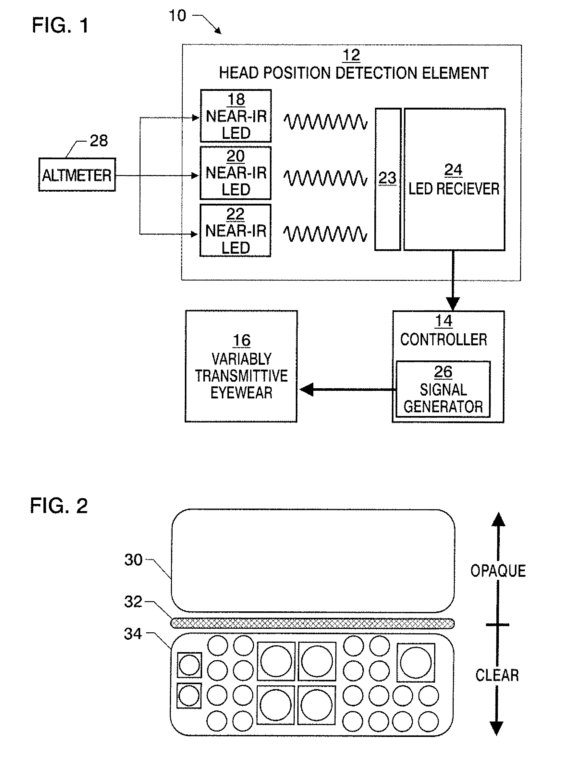
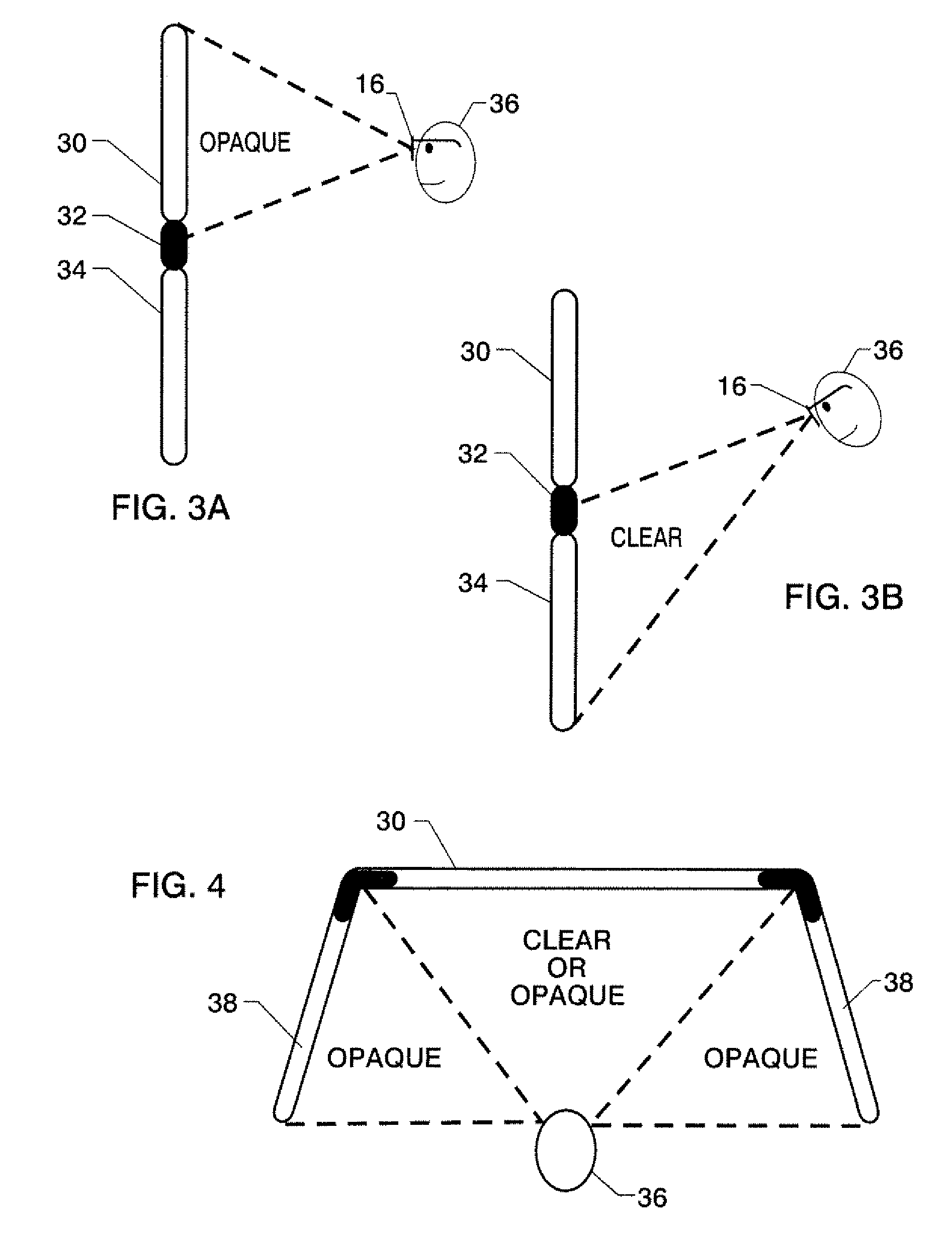
[0003]In one embodiment of the invention, a system for selectively obscuring a user's vision comprises a head position detection element for detecting a position of the user's head, eyewear having variably transmittive lenses, and a controller. The controller is configured to receive user head position information from the head position detection element and to control the transmittivity of the lenses based on the user head position information by varying an electrical signal applied to the lenses. The user head position information may comprise information regarding an up and down position of the user's head relative to a predetermined point in space in front of the user. As such, the controller may be configured to reduce the transmittivity to darken the lenses and thereby obscure the user's vision when the user's up and down head position is above the predetermined point in space, and to increase the transmittivity to lighten the lenses and thereby not obscure the user's vision when the user's up and down head position is below the predetermined point in space. The predetermined point in space may be at a border between a windscreen and an instrument panel of an aircraft. The controller may be configured to control the transmittivity of the lenses by varying at least one of an amplitude or a duty cycle of the electrical signal applied to the lenses.
[0004]Additionally, the user head position information may comprise information regarding a left and right position of the user's head relative to a predetermined point in space in front of the user. As such, the controller may be configured to reduce the transmittivity to darken the lenses and thereby obscure the user's vision when the user's left and right head position is more than a predetermined distance from the predetermined point in space.
[0007]The system may be further configured to receive aircraft altitude information and to increase the transmittivity to lighten the lenses and thereby not obscure the user's vision when the aircraft altitude information indicates that the aircraft is below a predetermined altitude.

Problems solved by technology

There is a potential for disorientation by the use of such training techniques that otherwise complicates the task of instrument flight training.

Method used


Image

  • Variably Transmittive, Electronically-Controlled Eyewear
  • Variably Transmittive, Electronically-Controlled Eyewear
  • Variably Transmittive, Electronically-Controlled Eyewear

Examples


Embodiment Construction

[0015]The present invention now will be described more fully hereinafter with reference to the accompanying drawings, in which preferred embodiments of the invention are shown. This invention may, however, be embodied in many different forms and should not be construed as limited to the embodiments set forth herein; rather, these embodiments are provided so that this disclosure will be thorough and complete, and will fully convey the scope of the invention to those skilled in the art. Like numbers refer to like elements throughout.

[0016]The novel flight subsystem of embodiments of the invention performs the function of an “electronic hood” and is worn like glasses or goggles. The pilot eyewear of embodiments of the invention integrates variable opacity optical elements into comfortable glasses, goggles, or any suitable eyewear. This has been accomplished through the use of custom lens structures employing a transmissive-type twisted nematic liquid crystal polymer layer as an electro...


PUM


Abstract

A system and method for flight training and evaluation of pilots comprises electronically activated vision restriction glasses that detect the pilot's head position and automatically darken and restrict the pilot's ability to see through the front and side windscreens when the pilot-in-training attempts to see out the windscreen. Thus, the pilot-in-training sees only within the aircraft cockpit, forcing him or her to fly by instruments in the most restricted operational mode.

Description

FIELD OF THE INVENTION[0001]The present invention generally relates to electronically-controlled eyewear of variable transmittivity and, more particularly, relates to eyewear capable of selectively obscuring a user's vision for training, eye protection, and the like.BACKGROUND OF THE INVENTION[0002]Pilots require or benefit from instrument-only training in order to prepare for poor visibility conditions or in-air emergencies. Specific pilot training and evaluation procedures for instrument flight rating qualification currently involves the use of an opaque hood draped across an aircraft's wind screen to restrict or obscure the student pilot's vision during instrument-only flight sessions. Another alternative training technique is the use of a face mask worn by the pilot in training which greatly restricts the pilot's peripheral vision but also prevents the pilot from seeing the entire instrument panel without moving his or her head. There is a potential for disorientation by the use...

Claims


Application Information

Patent Timeline
IPC IPC(8): G09B9/36G02F1/17G02F1/1335
CPCG09B9/30G09B9/36G09B9/307
Inventor CHAPMAN, JOHN J.GLAAB, LOUIS J.SCHOTT, TIMOTHY D.HOWELL, CHARLES T.FLECK, VINCENT J.
Owner NASA
Learn More