Eureka AIR delivers breakthrough ideas for toughest innovation challenges, trusted by R&D personnel around the world.

Wind turbine with mixers and ejectors

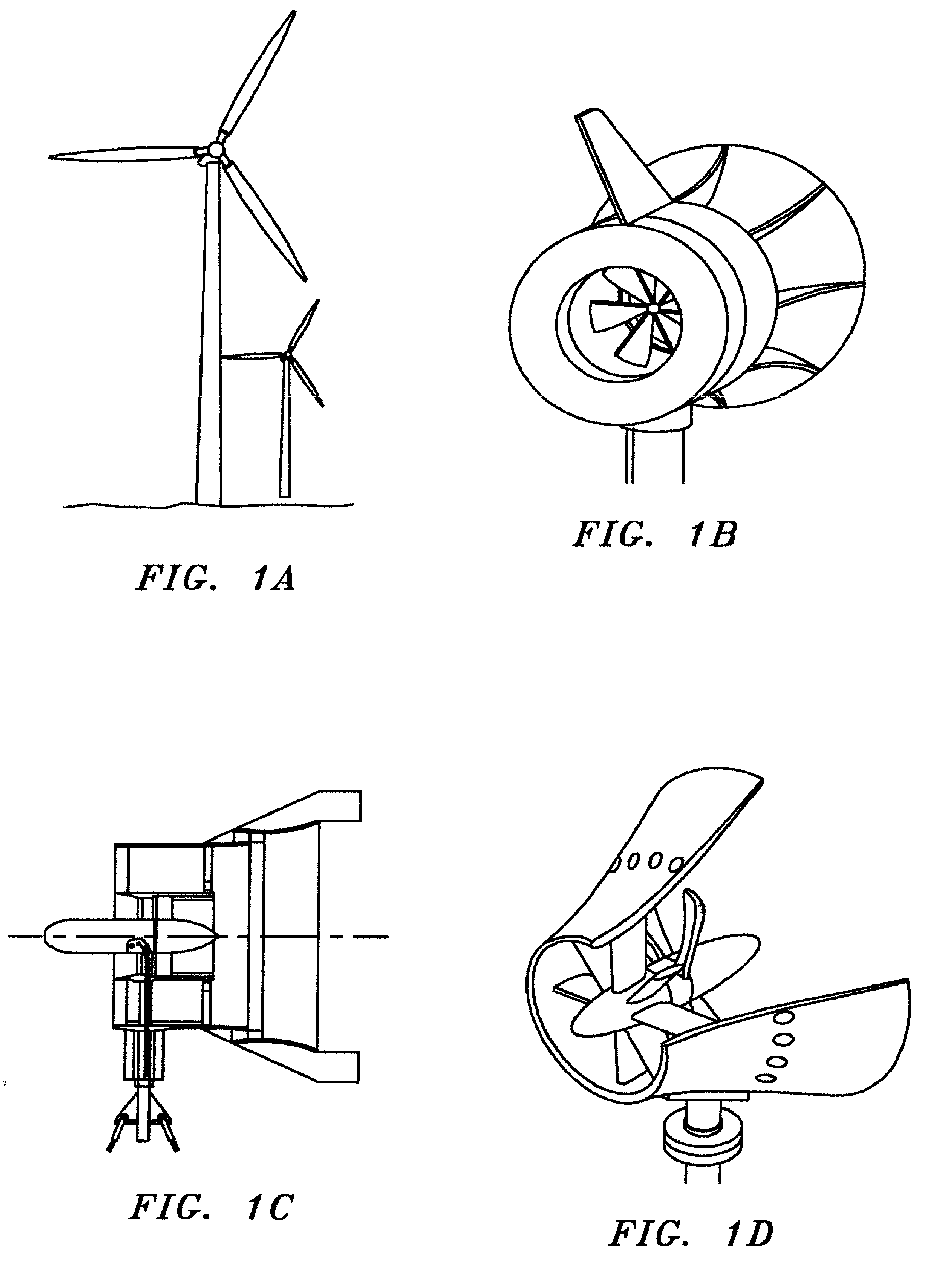
a wind turbine and mixer technology, applied in the direction of machines/engines, stators, liquid fuel engines, etc., can solve the problems of significant bird strikes and kills, poor performance at low wind speed, irritating pulsating noise, etc., and achieve the effect of increasing the productivity of wind farms

Inactive Publication Date: 2009-12-24
FLODESIGN WIND TURBINE
View PDF59 Cites 16 Cited by
  • Summary
  • Abstract
  • Description
  • Claims
  • Application Information

AI Technical Summary

Benefits of technology

[0030]First-principles-based theoretical analysis of the preferred MEWT indicates that the MEWT can produce three or more time the power of its un-shrouded counterparts for the same frontal area, and increase the productivity of wind farms by a factor of two or more.

Problems solved by technology

(1) Poor performance at low wind speeds, which is most relevant because a majority of the “good-wind” sites have been taken up and the industry has had to begin focusing on technologies for “small wind” sites,
(2) Safety concerns due to poor containment for damaged propellers and shielding of rotating parts,
(3) Irritating pulsating noise that can reach far from the source,
(4) Significant bird strikes and kills,
(5) Significant first and recurring costs due to:(i) expensive internal gearing, and(ii) expensive turbine blade replacements caused by high winds and wind gusts, plus
(6) Poor and / or unacceptable esthetics for urban and suburban settings.
The underlying cause for the problems and limitations listed above is that the vast majority of existing wind turbine systems depend on the same design methodology.
As a result, virtually all existing wind turbines are unshrouded / unducted, have only a few blades (which tend to be very long, thin and structurally vulnerable) and rotate at very low blade-hub speeds (thus requiring extensive internal gearing for electricity production) but have very high blade-tip speeds (with its attendant complications).
This theory sets the current family of designs and leaves very little room for improving the aerodynamic performance.
In general, for a properly designed rotor, this increased flow speed causes more force on the rotor and subsequently higher levels of power extraction.
Often though, the rotor blades break apart due to the shear and tensile forces involved with higher winds.
Such claims however have not been sustained in practice and existing test results have not confirmed the feasibility of such gains in real wind turbine application.
However, as yet, none have been successful enough to have entered the marketplace.
This is apparently due to three major weaknesses of current designs: (a) they generally employ propeller based aerodynamic concepts versus turbine aerodynamic concepts, (b) they do not employ concepts for noise and flow improvements, and (c) they lack a first principles based ducted wind turbine design methodology equivalent to the “Betz / Schmitz Theory” that has been used extensively for unducted configurations.
Gas turbine technology has yet to be applied successfully to axial flow wind turbines.
Both of these effects result in low flow through, turbine velocities.
These low velocities minimize the potential benefits of gas turbine technology such as stator / rotor concepts.
Diffusers require long lengths for good performance, and tend to be very sensitive to oncoming flow variations.
Such long, flow sensitive diffusers are not practical in wind turbine installations.
Short diffusers stall, and just do not work in real applications.
Also, the downstream diffusion needed may not be possible with the turbine energy extraction desired at the accelerated velocities.
These effects have doomed all previous attempts at more efficient wind turbines using gas turbine technology.

Method used


Image

  • Wind turbine with mixers and ejectors
  • Wind turbine with mixers and ejectors
  • Wind turbine with mixers and ejectors

Examples


Embodiment Construction

[0067]In a one-dimensional actuator disc model, the turbine or propeller's effect is taken as a discontinuous extraction or addition of power. FIG. 27 provides the geometry and nomenclature for the more general ducted case. The unducted case is recovered when the duct size and the attendant force Fs are allowed to shrink to zero. Using a control volume analysis that includes the turbine / propeller blade as a discontinuity as well as the inflows and outflows at upstream and downstream infinity, the conservation of mass, momentum and energy for a low speed and / or incompressible fluid leads to the equations for power and thrust as:

PowerP=14ρAp(Vo2-Va2)(Vo+Va)Equation(1)ThrustT=2P / (Vo+Va)Equation(2)

[0068]The equations are first presented in dimensional form and later non-dimensionalized per their application. As seen, there are four variables, power P, thrust T, free stream velocity, Va and the downstream core velocity, Vo. For wind / water turbines, only forward velocity Va is known thus ...


PUM


Abstract

A Mixer / Ejector Wind Turbine (“MEWT”) system is disclosed which routinely exceeds the efficiencies of prior wind turbines. Unique ejector concepts are used to fluid-dynamically improve many operational characteristics of conventional wind turbines for potential power generation improvements of 50% and above. Applicants' preferred MEWT embodiment comprises: an aerodynamically contoured turbine shroud with an inlet; a ring of stator vanes; a ring of rotating blades (i.e., an impeller) in line with the stator vanes; and a mixer / ejector pump to increase the flow volume through the turbine while rapidly mixing the low energy turbine exit flow with high energy bypass wind flow. The MEWT can produce three or more time the power of its un-shrouded counterparts for the same frontal area, and can increase the productivity of wind farms by a factor of two or more. The same MEWT is safer and quieter providing improved wind turbine options for populated areas.

Description

RELATED APPLICATION[0001]This application is a continuation of U.S. patent application Ser. No. 12 / 054,050, filed Mar. 24, 2008. That application claims priority from Applicants' U.S. Provisional Patent Application Ser. No. 60 / 919,588, filed Mar. 23, 2007 (hereinafter “Applicants' Provisional Application”). Applicants hereby incorporate the disclosure of both applications by reference in their entirety.FIELD OF INVENTION[0002]The present invention deals generally with axial flow turbines, such as axial flow wind turbines.BACKGROUND OF INVENTION[0003]Improvements in the technology of electrical power generation by wind turbines are being sought throughout the world as part of the effort to reduce dependency on fossil fuels. The European Union has just announced a major sustainable energy project that includes significant use of wind power and is requesting the US to join this effort.[0004]To fully achieve the ultimate potential of such systems, several problems / limitations need to be...

Claims


Application Information

Patent Timeline
Patent Type & Authority Applications(United States)
IPC IPC(8): F03D7/04F03D1/04
CPCF03D1/04F05B2240/13Y02B10/30F05B2260/96Y02E10/721F05B2240/133Y02E10/728F03D13/20Y02E10/72
Inventor PRESZ, JR., WALTER M.WERLE, MICHAEL J.
Owner FLODESIGN WIND TURBINE
Why Eureka
Eureka Blog
Learn More