
Heating and cooling pad, control unit therefor, system and method

a technology of control unit and heat exchanger, which is applied in the direction of lighting and heating apparatus, contraceptives, instruments, etc., can solve the problems of high cost of variable voltage power supply, easy to fall off, and easy to fall off, and achieve high heat conductivity grease

Inactive Publication Date: 2009-12-17
THERMAQUATIC
View PDF22 Cites 67 Cited by
  • Summary
  • Abstract
  • Description
  • Claims
  • Application Information

AI Technical Summary

Benefits of technology

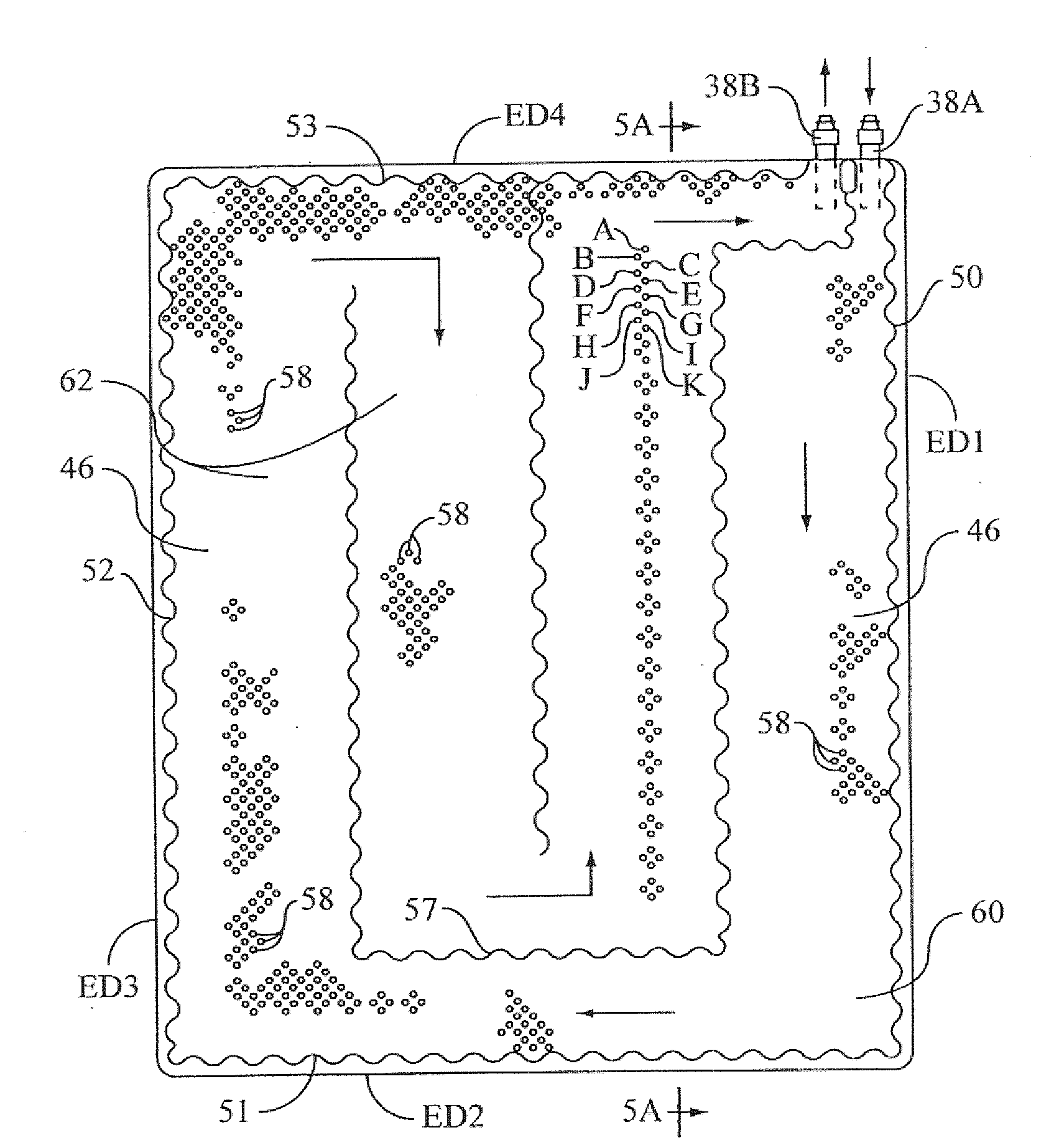
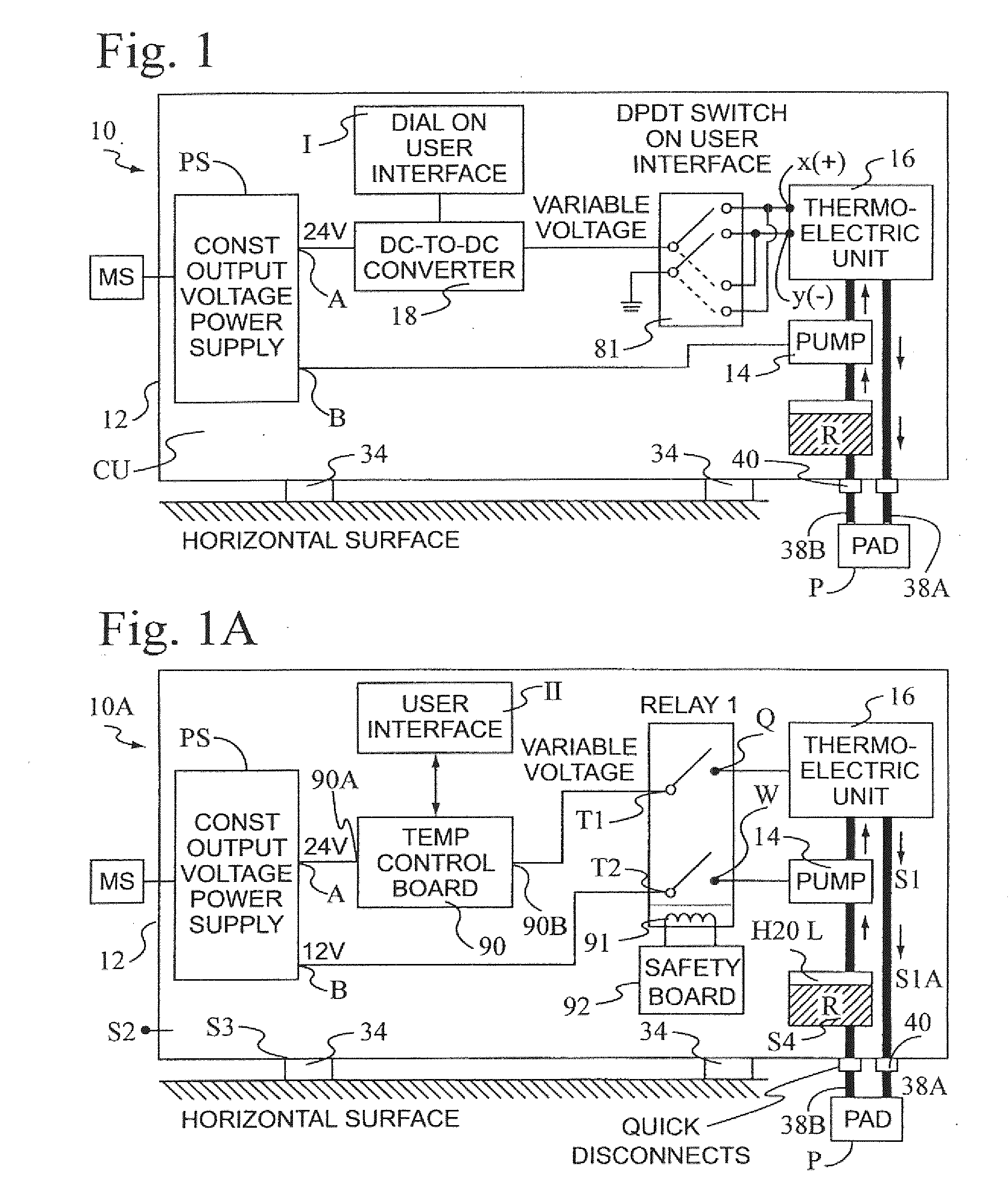
[0008]One, our heating and cooling system is lightweight, compact, portable, and may be operated at ambient air temperatures substantially from 41° F. to 122° F. It comprises a pad and control unit adapted to be placed in fluid communication with the pad. The control unit includes a housing having a reservoir for holding a heat transfer fluid and a fluid plumbing network for circulating the heat transfer fluid between an internal chamber of the pad and the reservoir. The fluid pressure within the chamber is at a predetermined level so the pad is comfortable to lie upon, for example, the fluid pressure within the chamber may be substantially from 3 to 20 pounds per square inch (psi). As directed by the user interacting with a user interface of the control unit, a bi-directional heat pump cools or heats the heat transfer fluid as the heat transfer fluid is circulated. The bi-directional heat pump may comprise a thermoelectric unit having a heating mode and cooling mode and through which the heat transfer fluid flows upon being circulated by a fluid pump between an inlet and an outlet of the pad's chamber.
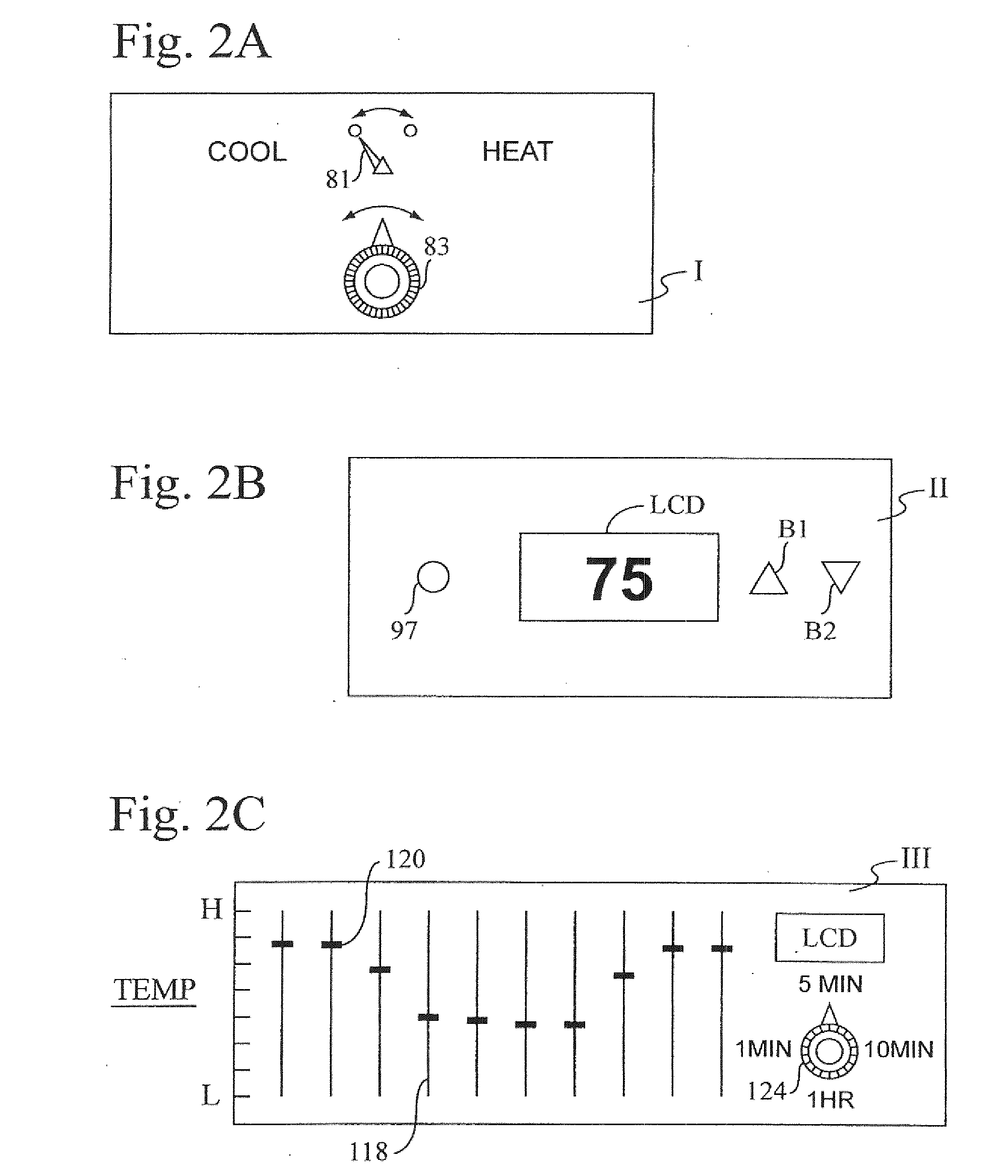
[0010]Three, a control circuit for operating the thermoelectric unit and heat transfer pump within the housing is coupled to the user interface. In one embodiment, the user interface enables the user to simply increase or decrease the temperature of the heat transfer fluid flowing through the chamber, but not select a specific temperature. In another embodiment, the user interface enables the user to select a specific temperature. In still another embodiment, the user interface enables the user to create a program in which a plurality of different temperatures are selected and selectively applied over a period of time. In other words, the user may create his or her own individualized custom temperature profile of the heat transfer fluid over a selected period of time. These temperature profiles may be varied for therapeutic purposes (hot / cold therapy), or for the purpose of prompting comfortable sleep, for example, by having the pad be warmer at the beginning of the sleep cycle, then cooling down during the middle of the night, varying temperature in a controlled manner over time.

Problems solved by technology

Moreover, particularly when sleeping, the temperature tends to rise, especially when the individual user is covered by a blanket or other bedding and the heating pad is under the user.
Thus, the problem which such conventional heating pads is that they are uncomfortable to lie upon and provide only heating.
In general, however, commercially available variable voltage power supplies are expensive.
Excessively high pressure may open the welds, causing the fluid to leak from the pad P, and make the pad too stiff and uncomfortable.
Excessively low pressure may result in a poor heat transfer to the user and cause the pad to be uncomfortable.

Method used


Image

  • Heating and cooling pad, control unit therefor, system and method
  • Heating and cooling pad, control unit therefor, system and method
  • Heating and cooling pad, control unit therefor, system and method

Examples


Embodiment Construction

.” The claims that follow define our pad, control unit therefor, system, and method, distinguishing them from the prior art; however, without limiting the scope of our pad, control unit therefor, system, and method, as expressed by these claims, in general terms, one or more, but not necessarily all, of their features are:

[0008]One, our heating and cooling system is lightweight, compact, portable, and may be operated at ambient air temperatures substantially from 41° F. to 122° F. It comprises a pad and control unit adapted to be placed in fluid communication with the pad. The control unit includes a housing having a reservoir for holding a heat transfer fluid and a fluid plumbing network for circulating the heat transfer fluid between an internal chamber of the pad and the reservoir. The fluid pressure within the chamber is at a predetermined level so the pad is comfortable to lie upon, for example, the fluid pressure within the chamber may be substantially from 3 to 20 pounds per ...


PUM


Abstract

A personal, portable heating and cooling system for an individual includes a thin, flexible pad and a control unit in fluid communication with the pad for regulating the temperature of a heat transfer fluid flowing between the pad and the control unit. The pad has an internal chamber for holding the heat transfer fluid. The chamber is partitioned to form therein a passageway that directs the heat transfer fluid to flow there through along a circuitous path. The control unit has a housing enclosing a reservoir for holding the heat transfer fluid, a pump for pumping the heat transfer fluid between the reservoir and the internal chamber of the pad, and a heating and cooling apparatus for regulating the temperature of a heat transfer fluid flowing between the reservoir and the chamber. The control unit includes an electronic control circuit having a user interface that enables a user increase and decrease the temperature of the fluid. An alternate embodiment enables the user to select a temperature of the fluid and still another embodiment where the temperature varies over time in accordance with an individualized custom temperature profile.

Description

[0001]This application is continuation-in-part application of PCT Application No. PCT / IB2007 / 004595, filed Dec. 24, 2007, entitled “Heating and Cooling Pad, Control unit Therefor, System and Method,” which claims the benefit under 35 USC 119(e) of U.S. Provisional Patent Application No. 60 / 877,098, entitled “Thermal Electric Heating And Cooling Liquid Circulating Pad,” filed Dec. 26, 2006. This related application is incorporated herein by reference and made a part of this application. If any conflict arises between the disclosure of the invention in this PCT application and that in the related provisional application, the disclosure in this utility application shall govern. Moreover, any and all U.S. patents, U.S. patent applications, and other documents, hard copy or electronic, cited or referred to in this application are incorporated herein by reference and made a part of this application.DEFINITIONS[0002]The words “comprising,”“having,”“containing,” and “including,” and other f...

Claims


Application Information

Patent Timeline
Patent Type & Authority Applications(United States)
IPC IPC(8): A61F7/08F25B21/02F25B29/00G05D23/00
CPCA61F7/007A61F2007/0054A61F2007/0076A61F2007/0295A61F2007/0093A61F2007/0096A61F2007/0274A61F2007/0086
Inventor PATIENCE, THEODORE ARTHURHAGHI, MEHRDAD
Owner THERMAQUATIC
Learn More