Eureka AIR delivers breakthrough ideas for toughest innovation challenges, trusted by R&D personnel around the world.

Modular gravity feed storage and dispensing assembly

a gravity feed and module technology, applied in the direction of instruments, transportation and packaging, apparatus for dispensing discrete objects, etc., can solve the problems of difficult assembly, overly limited storage capacity, and high manufacturing cos

Inactive Publication Date: 2009-12-17
MERCHANDISING RESOURCES
View PDF22 Cites 39 Cited by
  • Summary
  • Abstract
  • Description
  • Claims
  • Application Information

AI Technical Summary

Benefits of technology

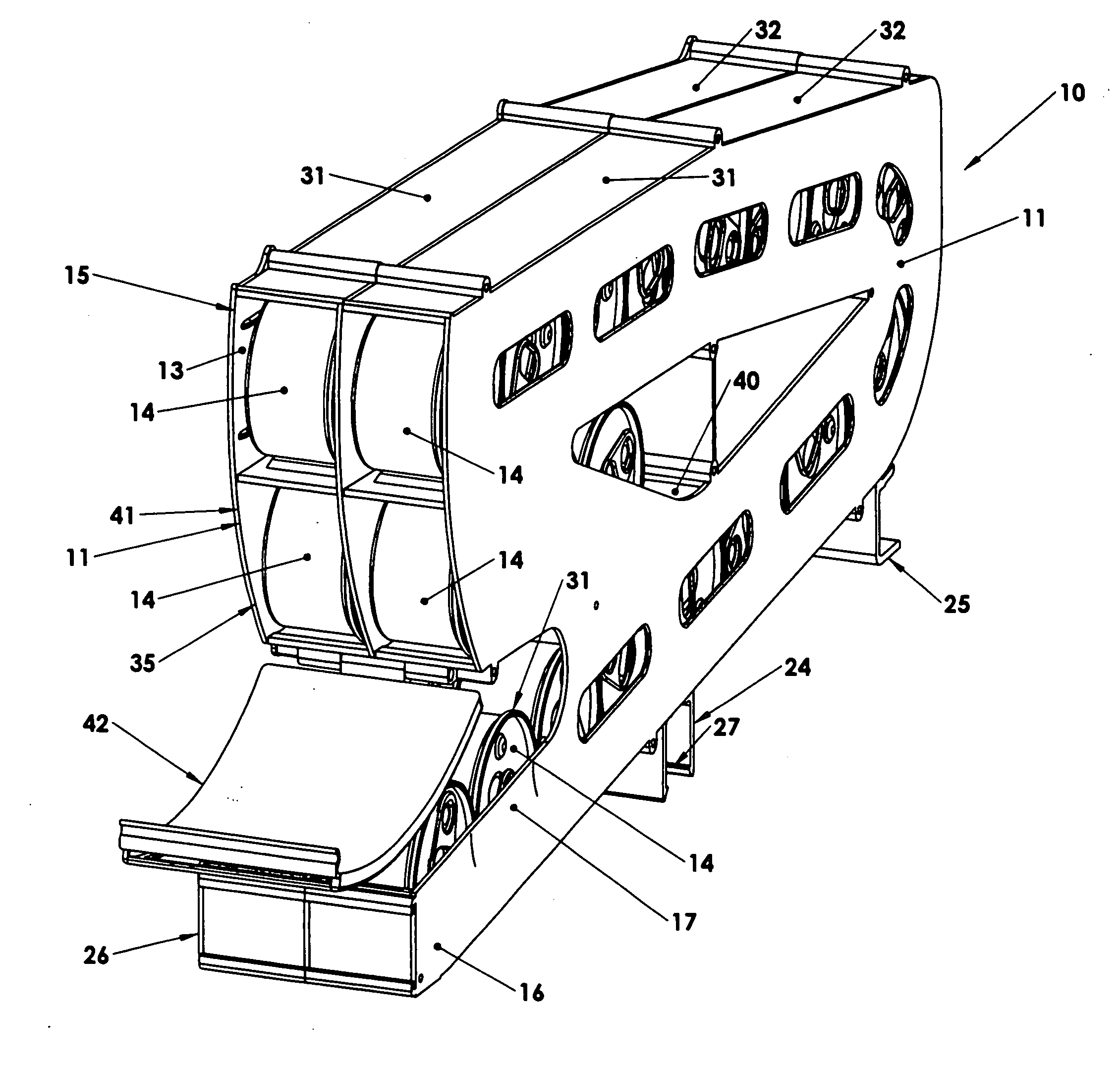
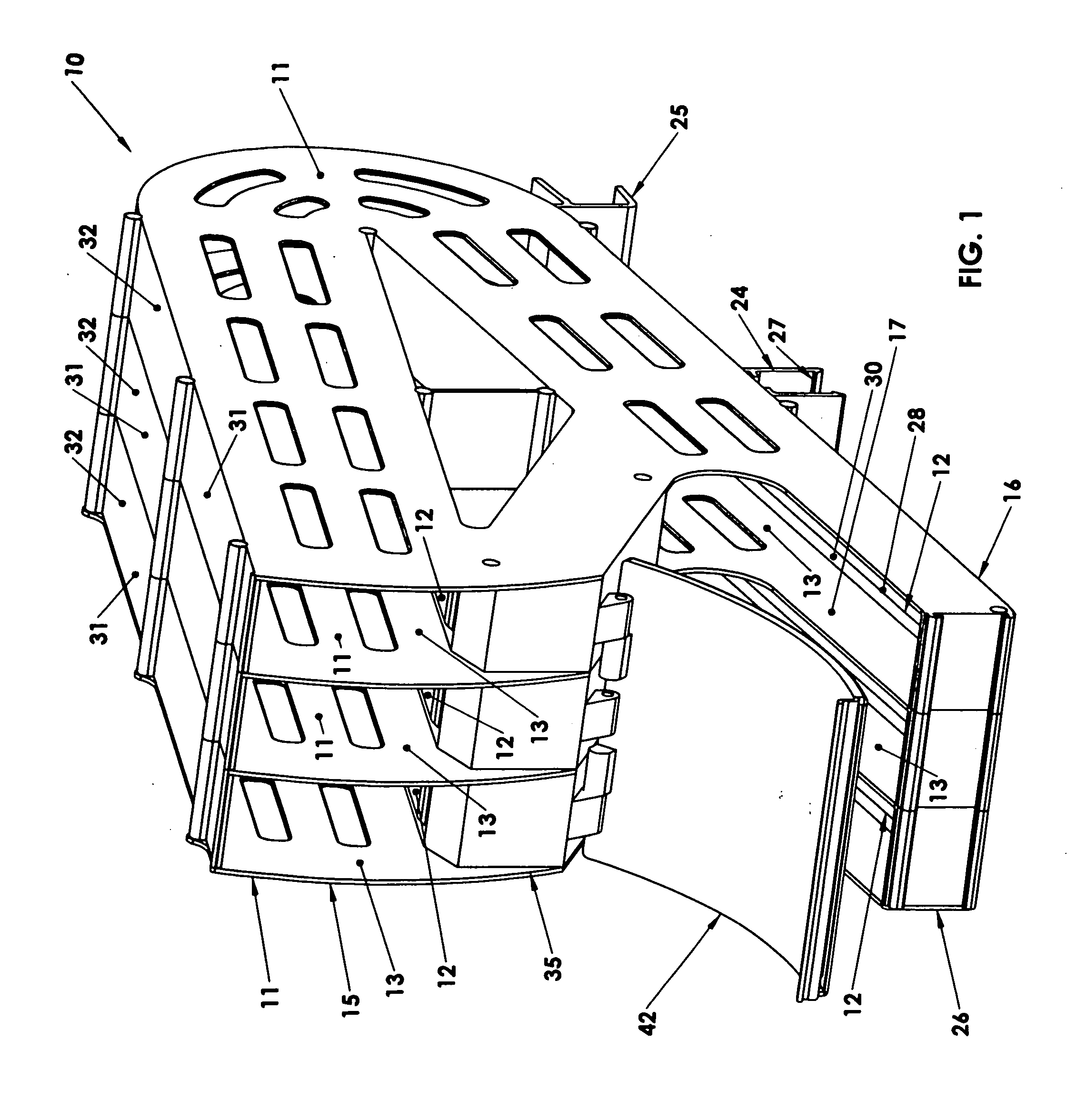
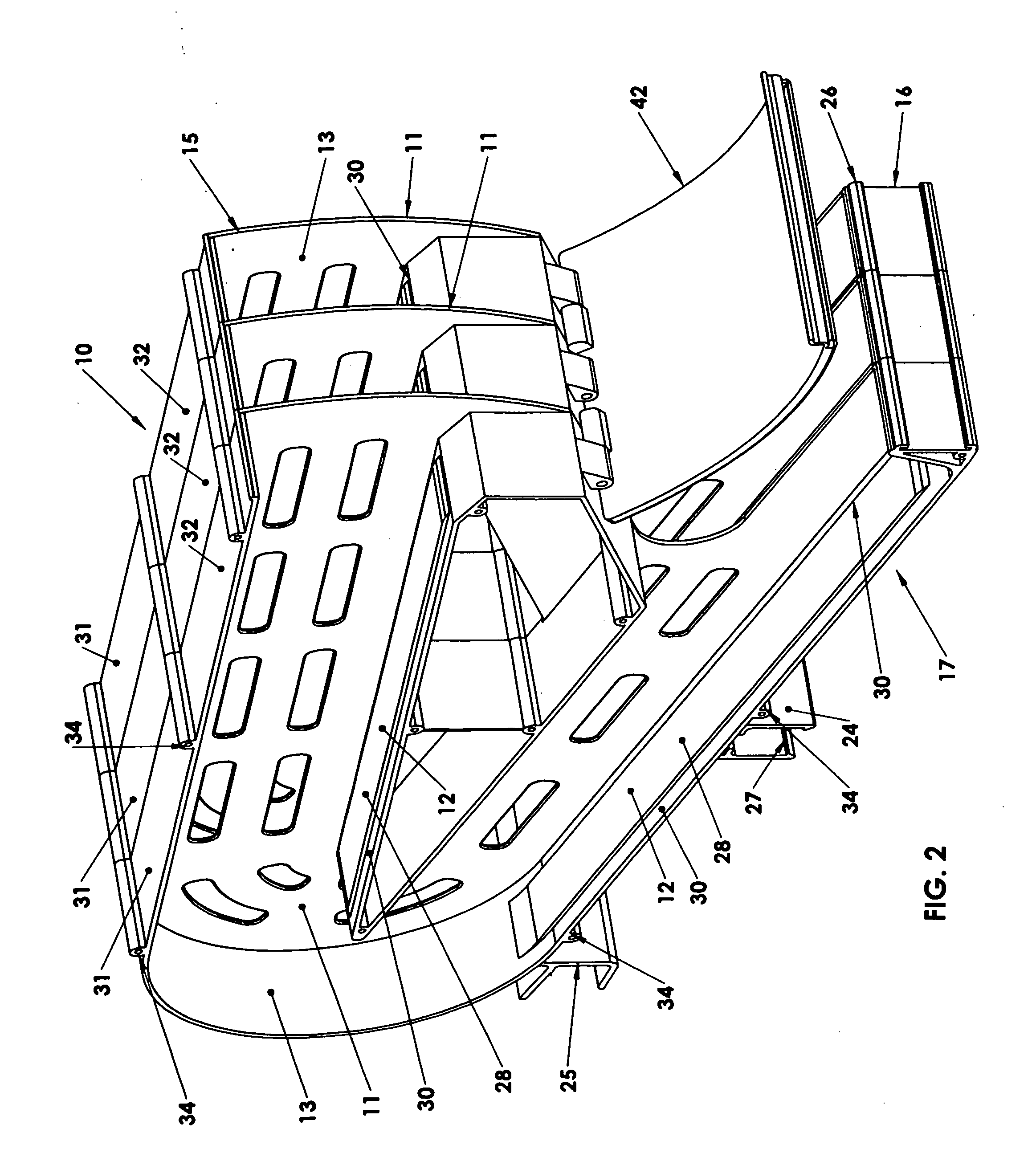
[0006]In one embodiment of the present invention a parallel pair of spaced and horizontally disposed elongated shelf bars, supported on opposite ends, are provided as front and rear dispenser support bars. Spaced front and rear support saddles depend downwardly from the dispenser and are positioned to respectively register over the front and rear support bars, with a front portion of the dispenser containing the removal area overhanging the front dispenser support bar. The rear support saddles have a rearward facing C-shaped configuration dimensioned and contoured to slide rearwardly over the rear support bar, and the front support saddles have a downwardly facing C-shaped configuration dimensioned and contoured to slide downwardly over the front support bar after the rear support saddle has been slid into position over the rear support bar, whereby the dispenser is thereby prevented from sliding or tipping over in the forward direction.
[0007]The rear support bar may be positioned higher than the front support bar in order to more favorably present the articles to be dispensed, to create maximum storage space within the dispenser, and to provide more incline for better stock feed. The front support saddle or saddles may be provided with opposed inwardly extending protrusions on distal ends of the front saddle which are positioned and dimensioned to protrude slightly under the front support bar for thereby serving as a removal resistant detention of the front saddle from the front bar. This serves as a safety feature to resist accidental dislodgement of the dispensers from the support bars.
[0008]A second embodiment of the present invention provides the ramp assembly with a central raised ramp surface running with the chute for engagement with a rolling article to be dispensed, and side relief channels on opposite sides of the ramp surface to receive annularly protruding end rims of an article rolling down the ramp surface whereby the article will always be in rolling contact with the ramp surface. For example, when dispensing cans of typical construction which include top and bottom rolled end rims that extend further in diameter than the side of the can, the can will freely roll on its side down the ramp surface as the end rims cannot interfere as they are provided with relief by permitting them to protrude into the side relief channels on opposite sides of the ramp surface.
[0010]An additional feature to this embodiment may be provided in the form of including a secondary ramp assembly which is also slightly inclined to receive rolling stock at an upper end thereof. This secondary ramp assembly is positioned under the upper portion of the chute but above the lower portion for storing extra articles thereon in otherwise unused space between the upper and lower portions of the chute. This permits the storage of additional stock in a space which is otherwise normally left vacant. A hinged access door is provided to cover the stock access area and also the upper end of the secondary ramp assembly. This hinged door is provided with removable exterior advertising display indicia on the door for indicating and advertising the article contained in the chute. As with the prior art assemblies, a hinged access door will normally also be provided to cover the stock access area of the dispenser of the present invention, and provided with removable exterior advertising display indicia on the door for indicating the article contained in the chute. If desired, this hinged access door may be provided with different or unusual contours to assist in distinguishing one product or article contained therein from another dispenser containing a different article.

Problems solved by technology

Problems encountered with prior art modular display racks or assemblies are that such assemblies are overly limited in storage capacity, conform to conventional shelving systems when in fact there are better alternatives, are difficult to relocate from one shelf section to another when it is desired to move the produce, they are too expensive to manufacture and difficult to assemble, and the articles do not always freely flow down the chutes.
When store resets are required with some of the prior art systems, the product must be emptied from the assemblies before moving them and the assemblies must be disassembled and are difficult to reassemble.

Method used


Image

  • Modular gravity feed storage and dispensing assembly
  • Modular gravity feed storage and dispensing assembly
  • Modular gravity feed storage and dispensing assembly

Examples


second embodiment

[0023]the present invention is provided in the ramp assembly 12 which is provided with a central raised ramp surface 28 running with each chute 13 for engagement with a rolling article 14 to be dispensed. Side relief channels 30 are provided on opposite sides of ramp surface 28 to receive annularly protruding end rims 31 of each article 14 rolling down the ramp surface 28 whereby the article 14 will always be in rolling contact with the ramp surface 28.

third embodiment

[0024]the present invention is provided in that each vertically disposed panel 11 is provided with a horizontally extending ledge 31 protruding in one direction therefrom for thereby providing the entire of the ramp assembly 12. In other words, each vertically disposed panel 11 is integrally or unitarily molded with a ledge 31 to provide a unitarily molded subassembly 32. Accordingly, in order to assemble a three-chute dispenser 10 as illustrated in FIGS. 1 and 2, three of these molded subassemblies 32 are secured side by side together by any conventional means, such as by snap fit conventions, (here by self tapping screws received in molded screw passages 34) to provide the completed three-chute assembly. In order to close off the vertical face of the last subassembly 32, the last vertically disposed panel 11 in the form of cover panel 35 is secured in place. Accordingly, due to this ability to manufacture the dispensers 10 by the stacking of molded subassemblies, the manufacture t...


PUM


Abstract

A modular gravity feed storage and dispensing assembly including a dispenser having a plurality of spaced vertically disposed panels with a ramp assembly disposed between adjacent vertically disposed panels whereby a chute is provided between each of the adjacent panels for defining a travel path to guide articles traveling therealong between adjacent panels. The ramp assembly is slightly inclined so as to allow cylindrical articles to be rollingly advanced by means of gravity from an upper portion between the panels in the chute to a lower portion, and a removal area is disposed proximate the lower portion of the chute for allowing selective removal of one or more of the articles from the dispenser. A parallel pair of spaced and horizontally disposed elongated shelf bars are supported on opposite ends and provide front and rear dispenser support bars, and corresponding spaced front and rear support saddles depend downwardly from the dispenser and are positioned to respectively register over and engage the front and rear support bars instead of supporting the dispensers on a conventional shelf. Each ramp assembly includes a central raised ramp surface running with the chute for engagement with a rolling article to be dispensed, and side relief channels are provided on opposite sides of the ramp surface to receive annularly protruding end rims of an article, such as a can, rolling down the ramp surface whereby side surfaces of the article will remain in rolling contact with the ramp surface. Each vertically disposed panel of the dispenser is unitarily molded as a subassembly with a horizontally extending ledge which provides the entire ramp assembly.

Description

BACKGROUND OF THE INVENTION[0001]The present invention relates generally to a storage and dispensing assembly, and more particularly, a modular storage and dispensing assembly for dispensing rolling articles by gravity feed, such as cans and bottles.[0002]Gravity feed dispensers have been used in the product dispensing markets, ie., grocery stores, supermarkets, convenience marts and department stores, to provide on-shelf storage, automatic rotation of stock, and easy access for customers. The products are arranged on a rack which is inclined to horizontal such that when a customer removes one product at an end of a row of products, the entire row of products indexes forward one location equivalent to one product. The modular storage and dispensing assemblies of the prior art include a plurality of panels and connecting assembly for connecting adjacently disposed panels such that a chute is formed between each of the adjacently disposed upright panels. A rail or ramp assembly is pro...

Claims


Application Information

Patent Timeline
Patent Type & Authority Applications(United States)
IPC IPC(8): G07F11/00
CPCA47F1/087G07F11/30
Inventor SAINATO, ANTHONY V.NATCHER, JEFFREY H.
Owner MERCHANDISING RESOURCES
Why Eureka
Eureka Blog
Learn More