
Electrical connector having improved leds

a technology of leds and electrical connectors, applied in the field of module jacks, can solve problems such as space waste, and achieve the effect of preventing undesirable electrical connections and saving spa

Inactive Publication Date: 2009-12-10
HON HAI PRECISION IND CO LTD
View PDF4 Cites 4 Cited by
  • Summary
  • Abstract
  • Description
  • Claims
  • Application Information

AI Technical Summary

Benefits of technology

The present invention provides an electrical connector carrying LED pairs that occupy less space. The connector has a housing with multiple slots, LED pairs placed in the slots, and fixing portions that prevent electrical connection between the LEDs. The LEDs are positioned side-by-side in the slots, saving space. The technical effect is a more efficient use of space in the electrical connector.

Problems solved by technology

It would result in space waste, since each insertion slot is adapted for receiving one LED.

Method used


Image

  • Electrical connector having improved leds
  • Electrical connector having improved leds
  • Electrical connector having improved leds

Examples


Embodiment Construction

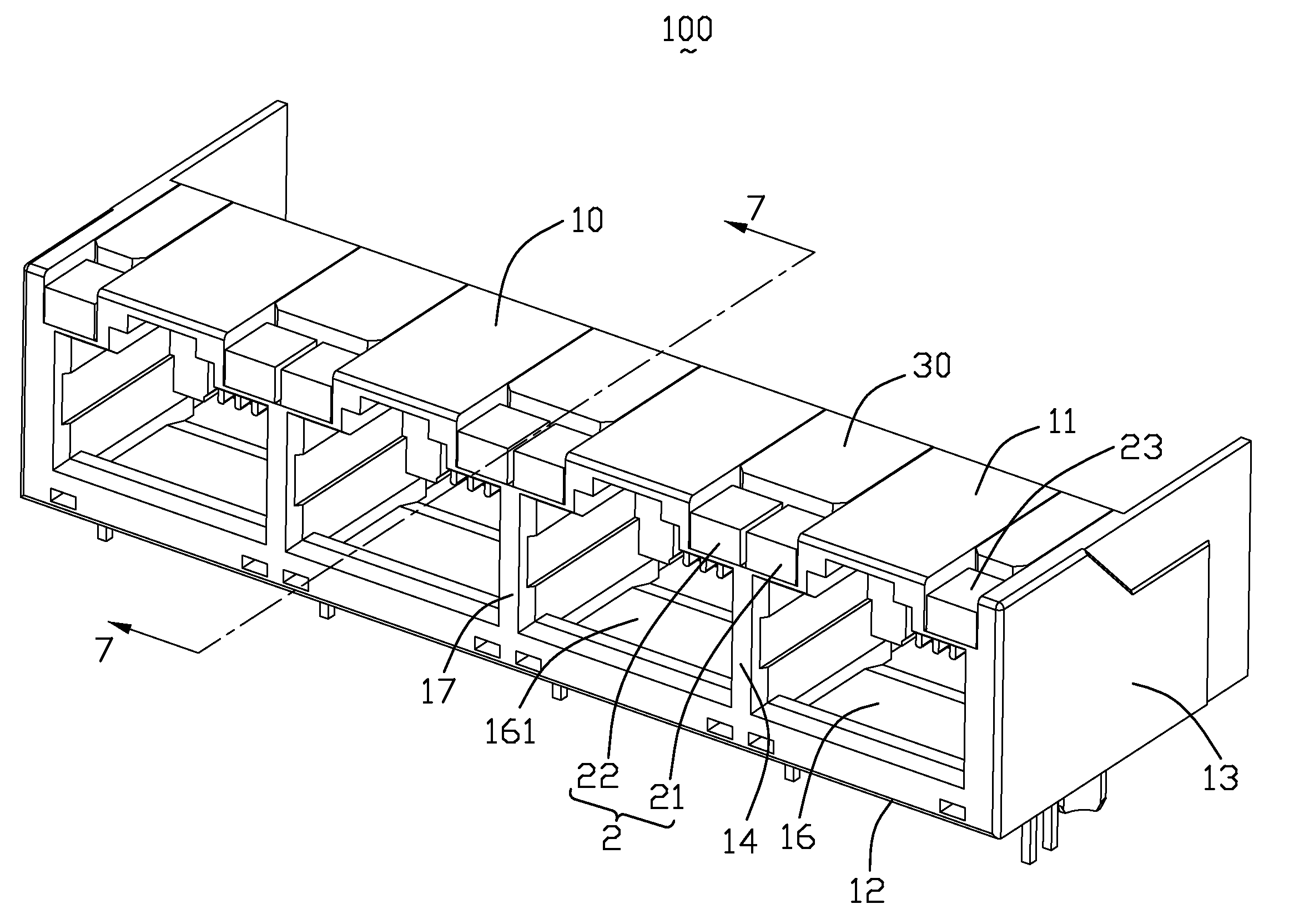
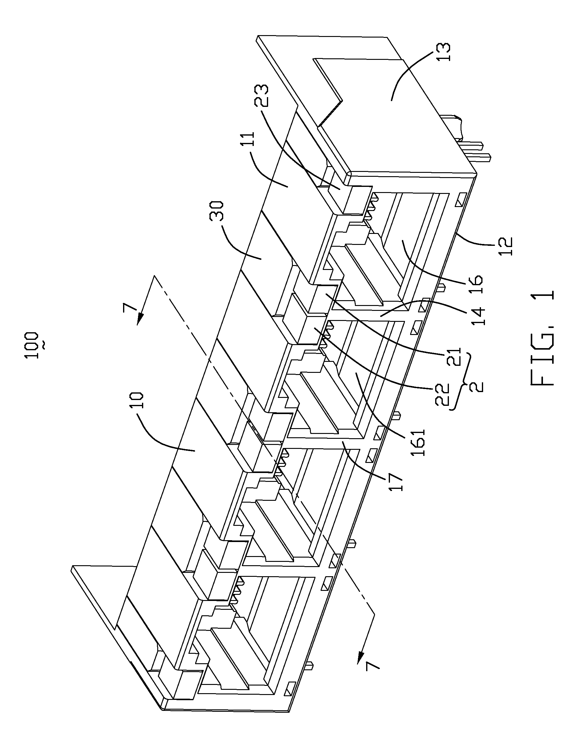
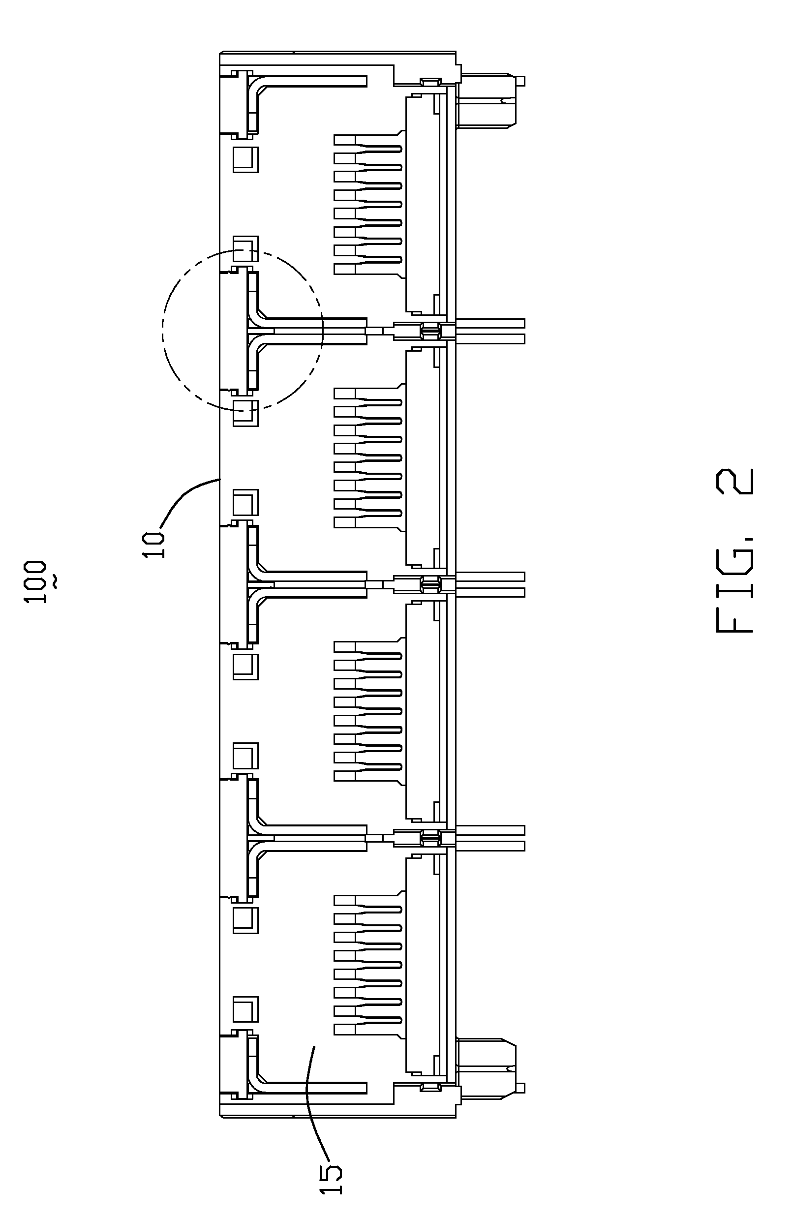
[0018]Reference will now be made in detail to the preferred embodiment of the present invention. Referring to FIGS. 1-3, an electrical connector 100 comprises an insulative housing 1, a plurality of terminal modules (not shown) received in the insulative housing 1, a plurality of LED pairs 20 and a pair of third LEDs 23 mounted in the insulative housing 1, and a plurality of fixing portions 30 mounted on the LED pairs 20 and third LEDs 23. The terminal modules and a shielding shell have been left out.

[0019]The insulative housing 1 comprises a bottom wall 12, a top wall 11 opposite to the bottom wall 12, a pair of periphery walls 13 perpendicular to the bottom wall 12, a plurality of mating ports 16 defined above the bottom wall 12, and a plurality of inner walls 17 each disposed between two adjacent mating ports 16. The insulative housing 1 further has a front face 14, a back face 15 opposite to the front face 14, a receiving cavity 161 defined in each mating port 16, a pair of firs...


PUM


Abstract

An electrical connector (100) includes an insulative housing (10) defining a number of insertion slots (112), a number of LED (Light Emitting Diode) pairs (20) received in the insertion slots, and a number of fixing portions (31) respectively inserted in the insertion slots. Each LED pair has a first and a second LEDs (21, 22) disposed side-by-side in one insertion slot to save space. Each fixing portion has a vertically extending spacer (311) disposed between the first and second LEDs of each LED pair to prevent undesirable electrical connection between the first and second LEDs.

Description

BACKGROUND OF THE INVENTION[0001]1. Field of the Invention[0002]The present invention relates to an electrical connector, and more particularly to a modular jack having a set of LEDs arranged side-by-side.[0003]2. Description of Related Art[0004]U.S. Pat No. 6,142,822 issued to Wu on Nov. 7, 2000 discloses an electrical connector having an insulative housing defining a pair of insertion slots, a pair of LEDs (Light Emitting Diodes) respectively inserted in the slots, a pair of fixing portions respectively mounted on the insertion slots for resisting against corresponding LEDs.[0005]It would result in space waste, since each insertion slot is adapted for receiving one LED.[0006]Hence, an electrical connector carrying improved LEDs is highly desired.SUMMARY OF THE INVENTION[0007]Accordingly, an object of the present invention is to provide an electrical connector carrying LED pairs, with LED pairs occupying less space.[0008]In order to achieve the object set forth, an electrical conne...

Claims


Application Information

Patent Timeline
Patent Type & Authority Applications(United States)
IPC IPC(8): H01R13/717
CPCH01R13/7175H01R24/64H01R2107/00
Inventor LIU, ZHI-JIAN
Owner HON HAI PRECISION IND CO LTD
Learn More