
Optical Scanning Device and Method for Determining Focus Position

a scanning device and focus position technology, applied in the field of optical scanning devices, can solve the problem that the focus position is not available along the optical axis, and achieve the effect of reducing the operation effect of the tilt servo

Inactive Publication Date: 2009-12-10
LITE ON IT
View PDF6 Cites 3 Cited by
  • Summary
  • Abstract
  • Description
  • Claims
  • Application Information

AI Technical Summary

Benefits of technology

[0007]The distance between the exit face of the objective system and focus of the radiation beam can be derived from the tilt signal, because properties of the tilt signal depend on this distance. Since the tilt signal is a very stable signal, it can provide a reliable value for the distance.

Problems solved by technology

A disadvantage of this known scanning device is that no signal is available representing the position of the focus along the optical axis.

Method used


Image

  • Optical Scanning Device and Method for Determining Focus Position
  • Optical Scanning Device and Method for Determining Focus Position
  • Optical Scanning Device and Method for Determining Focus Position

Examples


Embodiment Construction

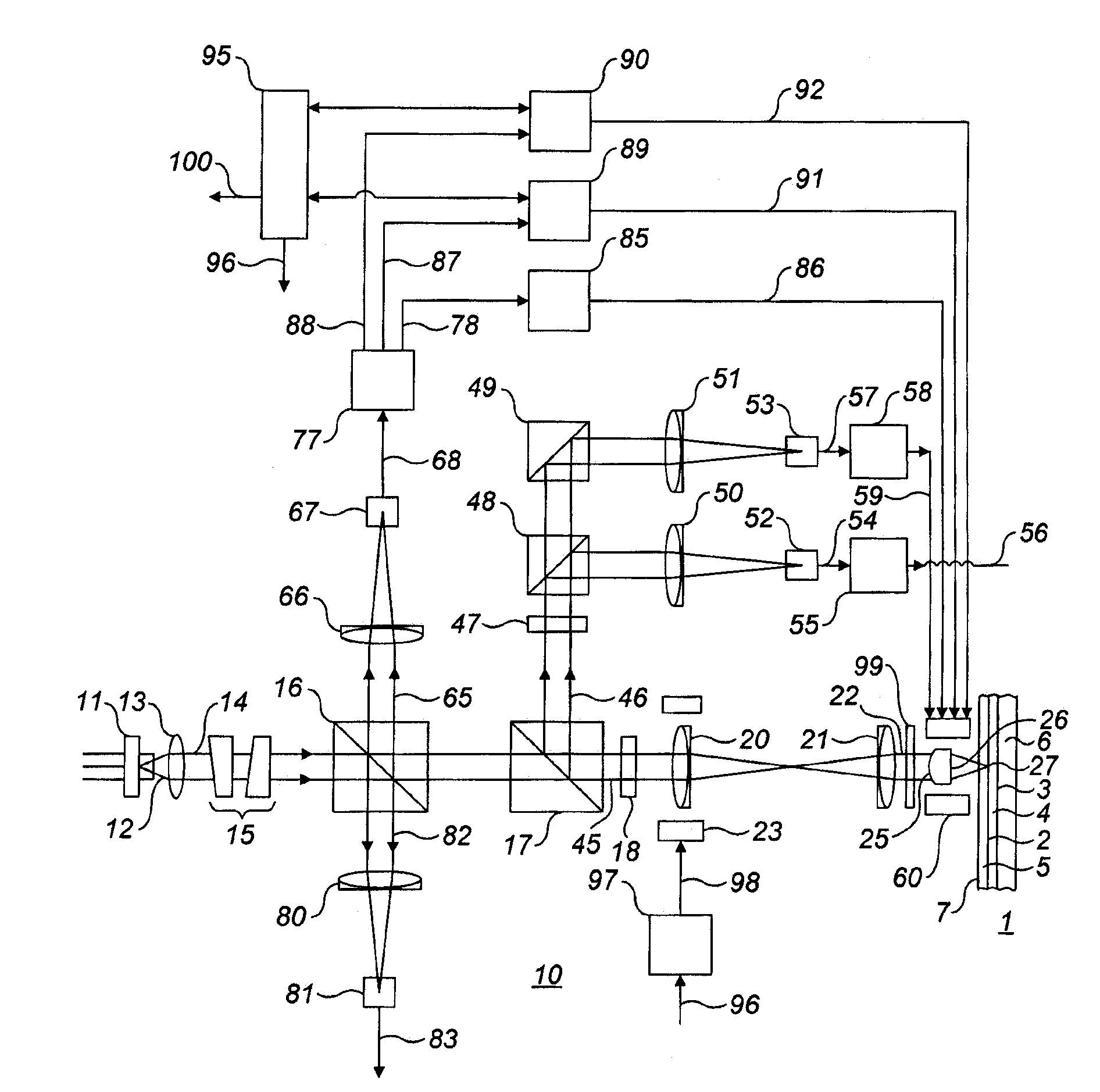
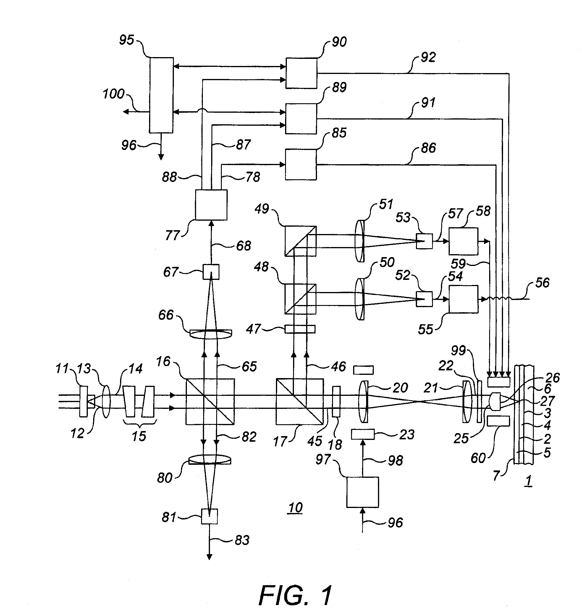
[0024]FIG. 1 shows schematically a record carrier and an optical scanning device for scanning a record carrier in accordance with an embodiment of the present invention.

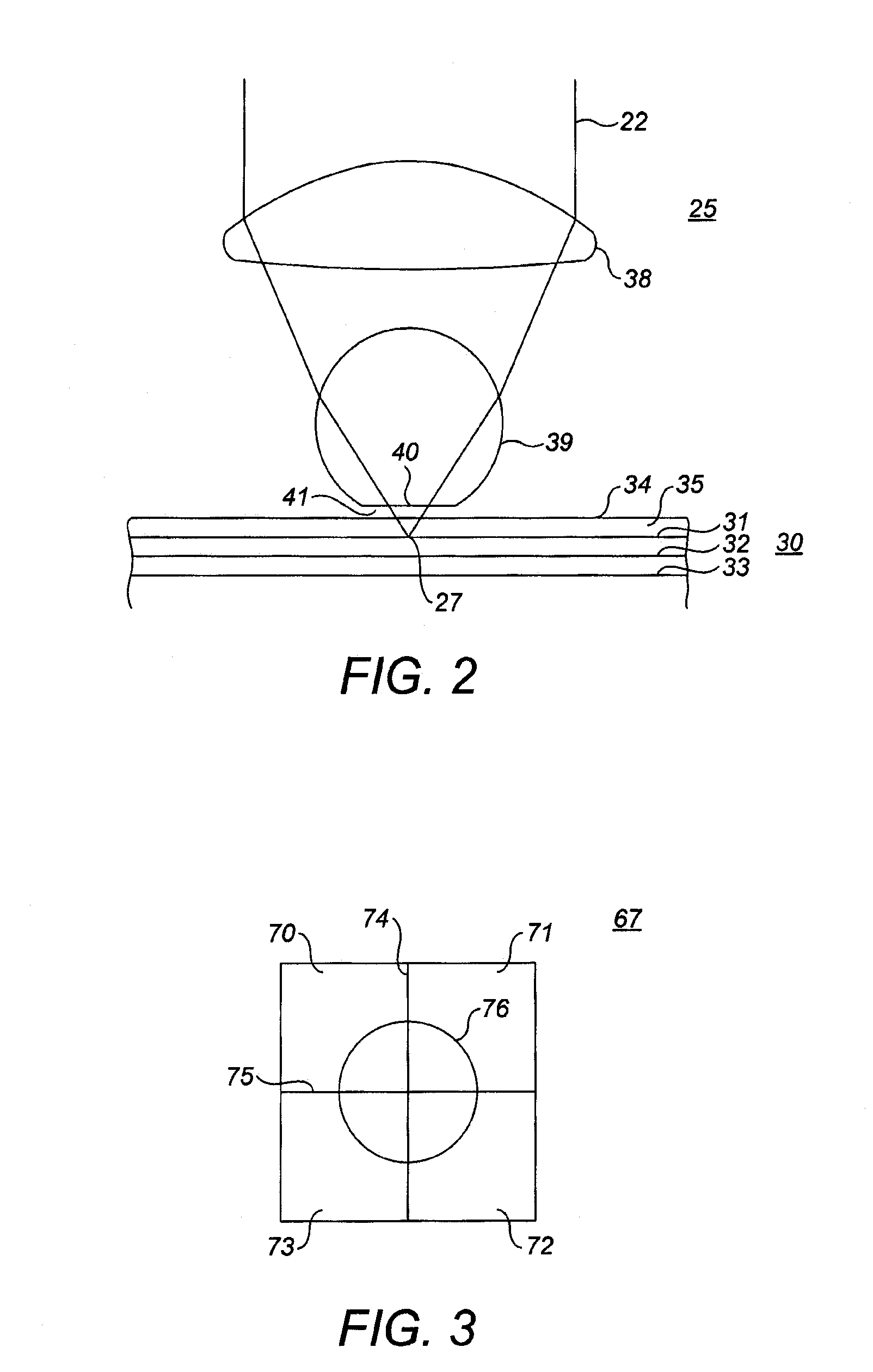
[0025]The record carrier 1 is to be scanned by the optical scanning device. The record carrier is of a multi-layer type, having two information layers 2 and 3 separated by a spacer layer 4. The information layer 2 may be protected from environmental influences by a cover layer 5. The information layers are arranged on a substrate 6, providing mechanical support for the layers. An outer face 7 of the record carrier faces the scanning device.

[0026]User information may be arranged in tracks in the information layers of the record carrier. For a disc shaped record carrier each of the tracks forms a 360° turn of a spiral. The tracks may include land and groove portions. The information is coded in the form of information areas having properties different from the surrounding areas to allow optical detection of the informa...


PUM

PropertyMeasurementUnit
distanceaaaaaaaaaa
wavelengthaaaaaaaaaa
depthaaaaaaaaaa

Abstract

The optical scanning device [10] is arranged for scanning a record carrier [1]. The record carrier has an outer face [7]. The scanning device comprises a radiation source [11] for generating a radiation beam [12] and an objective system [25] having an exit face [26] arranged for evanescent coupling of the radiation beam between the exit face and the outer face and for converging the radiation beam to a focus [27]. A tilt measuring system [67, 77] provides a tilt signal [87; 88] representing a tilt angle between the objective system and the record carrier. A control unit [95] determines a distance signal representing a distance between the exit face and the focus from the tilt signal.

Description

CROSS REFERENCE TO RELATED APPLICATION[0001]This application claims the benefit of priority under 35 U.S.C Section 119 from U.S. Provisional Patent Application Ser. No. 61 / 131,184, filed on Jun. 6, 2008.FIELD OF THE INVENTION [0002]The invention relates to an optical scanning device and to a method for determining a focus position in such a scanning device.BACKGROUND OF THE INVENTION [0003]International patent application WO 2006 / 018749 discloses a near-field optical scanning device for scanning a record carrier. In a near-field optical scanning device a radiation beam is transmitted across a gap between an exit face of an objective system and an outer face of the record carrier using evanescent coupling of the radiation. A gap servo keeps the size of the gap during scanning at a distance of approximately 25 nm. A tilt servo in the device controls the tilt angle between the objective system and the record carrier such that it is kept within a relatively tight tilt tolerance. This to...

Claims


Application Information

Patent Timeline
Patent Type & Authority Applications(United States)
IPC IPC(8): G11B27/36
CPCG11B7/0917G11B7/0956G11B2007/0013G11B7/13925G11B7/1387
Inventor BAKX, JOHANNES LEOPOLDUS
Owner LITE ON IT
Learn More