
Hybrid Orthopedic Implant

a hybrid and orthopedic technology, applied in the field of hybrid orthopedic implants, can solve the problems of difficult intraoperatively shaping plastic implants by bending or twisting, difficult for surgeons to cut, or shave, so as to avoid the disadvantages of tendon irritation, improve the effect of elasticity and strength, and prevent the effect of tendon irritation

Inactive Publication Date: 2009-12-03
SKELETAL DYNAMICS LLC (US)
View PDF11 Cites 84 Cited by
  • Summary
  • Abstract
  • Description
  • Claims
  • Application Information

AI Technical Summary

Benefits of technology

"The invention is a hybrid orthopedic implant that combines the benefits of metal and plastic materials to overcome their disadvantages. The metal skeleton provides strength and load-bearing ability, while the plastic covering allows for complex shapes and thin sections to adapt to the metaphysis and prevent tendon irritation. The implant has self-tapping properties and can be selectively used for different portions of the implant. The invention provides improved deformation properties, better manufacturing and shaping capabilities, and is not limited to the specific details shown."

Problems solved by technology

Plastic stabilization implants are used less frequently, as sufficient strength has generally not been available.
On the other hand, and because of their hardness, it is difficult for the surgeon to cut, or to shave, a metallic implant intraoperatively.
Metal implants are normally manufactured by machining or forging the metal into the desired shape; therefore, it is costly to manufacture into complex or very thin shapes.
On the other hand, it is difficult to intraoperatively shape plastic implants by bending or twisting, because of their poor malleability.
Because metal is difficult to manufacture into complex thin shapes and difficult to cut or shave in the operating room, it is often problematic to provide optimal buttress support with metal plates in those anatomically sensitive areas.

Method used


Image

  • Hybrid Orthopedic Implant
  • Hybrid Orthopedic Implant
  • Hybrid Orthopedic Implant

Examples


first embodiment

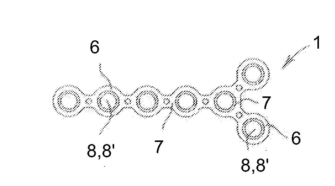
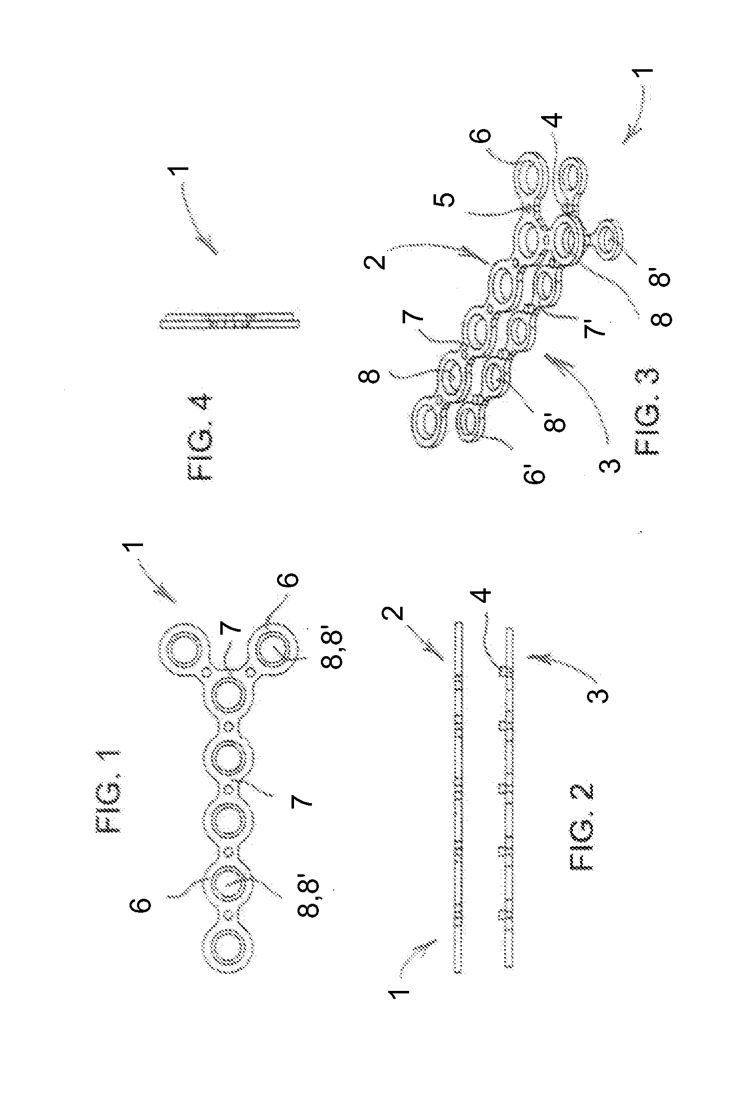
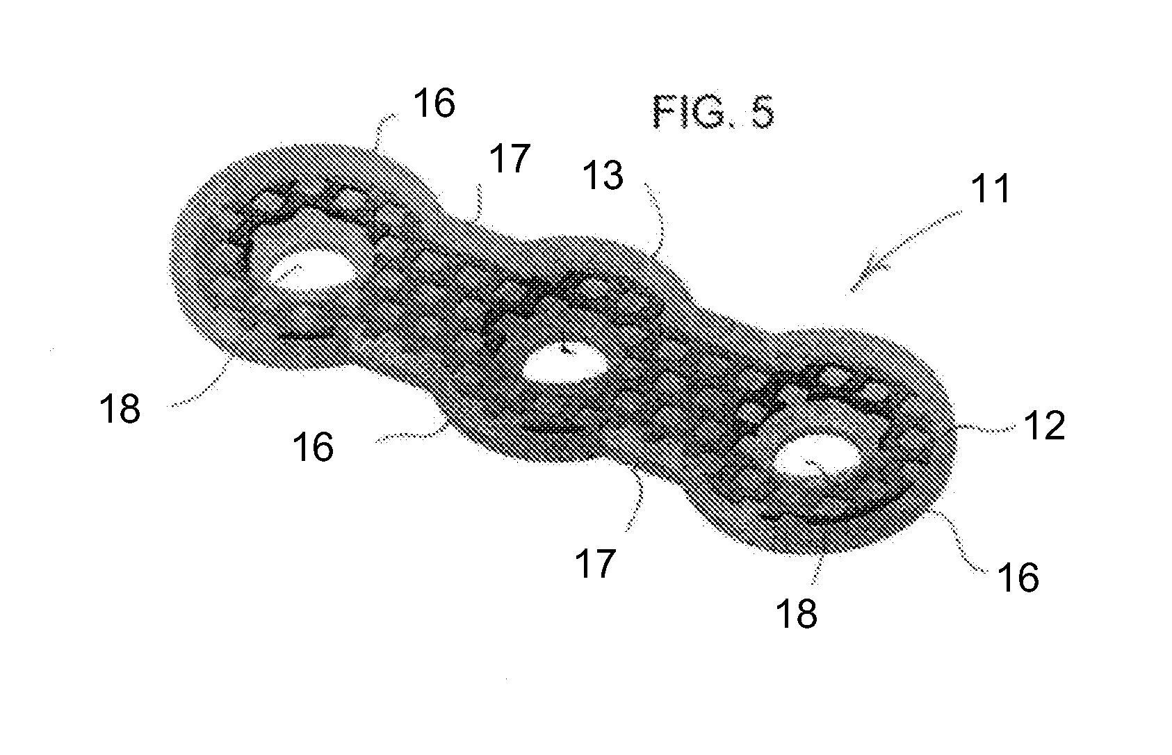
[0036]Referring now to the figures of the drawing in detail and first, particularly, to FIG. 1 thereof, there is seen a hybrid orthopedic plate 1 according to the invention. It may be seen from FIGS. 2, 3 and 4 that the plate 1 has a body with a metal skeleton 2 and a plastic layer 3. Bosses 4 protruding from the plastic layer 3 are snapped or otherwise secured in corresponding holes 5 in the metal skeleton 2 in order to lock the elements 2, 3 together, as seen in FIGS. 1 and 4. The metal skeleton 2 has nodes 6, internodes or webs 7 between the nodes 6 and holes 8 passing through the nodes 6. The plastic layer 3 has nodes 6′, internodes or webs 7′ between the nodes 6′ and holes 8′ passing through the nodes 6′. Each pair of holes 8, 8′ receive one screw to be screwed into a bone and, preferably, self-tap in angle-stable position into one or both the metal skeleton 2 and the plastic layer 3 for holding the screws affixed to the plate and the plate affixed to the bone. The plate 1 may ...

third embodiment

[0038]a hybrid plate 21 is illustrated in FIGS. 6-9. The plate 21 has a body with a trabecular or foam metal core or skeleton 22, for instance titanium, and a plastic layer 23, for instance PEEK, covering the metal core 22. Once again, as in the first two embodiments, the hybrid plate 21 has nodes 26, internodes or webs 27 and holes 28 in the nodes for receiving screws. The hybrid plate 21 may have any of the shapes mentioned above and may additionally include perforations or holes through the core 22, to facilitate intraoperative bending of the plate 21. In the embodiment show in FIG. 7 the perforations are roughly circular in cross-section, although other cross-sectional shapes and / or amorphous cross-sections can be used.

fourth embodiment

[0039]a hybrid plate 31 is illustrated in FIGS. 10-13. The hybrid plate 31 has a body with a metal core or skeleton 32, for example titanium, and a plastic layer 33, made, for example of PEEK, covering the metal core 32. The hybrid plate 31 has a head portion 36, a neck portion 37, a shaft portion 39 and holes 38 in the head and shaft portion for receiving screws. The metal core or skeleton 32 may include tines 32′ at the distal edge of the head portion to facilitate differential bending or shaping of the head portion of the plate by engaging one or more bending tools into engagement holes 32″ and exercising torque.


PUM


Abstract

A hybrid orthopedic implant is provided. The implant includes a hybrid plate including a metal skeleton engaged with a plastic covering. Holes passing through the hybrid plate receive screws therethrough, to secure the hybrid plate to bone.

Description

CROSS-REFERENCE TO RELATED APPLICATION[0001]The present application claims priority to the co-pending Provisional Patent Application No. 61 / 058,046, filed on Jun. 2, 2008 and entitled “Hybrid Orthopedic Implant”, which application is being incorporated herein, by reference, in its entirety.BACKGROUND OF THE INVENTION[0002]1. Field of the Invention[0003]The invention relates to a hybrid orthopedic implant.[0004]2. Description of the Related Art[0005]Orthopedic stabilization implants are commonly made out of metal. Plastic stabilization implants are used less frequently, as sufficient strength has generally not been available. Also, metal implants present the advantage of malleability; the surgeon can permanently change the shape of the implant to suit his needs by bending or twisting during application (intraoperatively). On the other hand, and because of their hardness, it is difficult for the surgeon to cut, or to shave, a metallic implant intraoperatively. Metal implants are norma...

Claims


Application Information

Patent Timeline
Patent Type & Authority Applications(United States)
IPC IPC(8): A61B17/80
CPCA61B17/80A61B17/8085A61B17/8057
Inventor ORBAY, JORGE L.NORMAN, THOMAS H.DE QUEVEDO, WILLIAM GARCIAESPINOSA, ALEJANDRO
Owner SKELETAL DYNAMICS LLC (US)
Learn More