
Wind Diverter

a wind turbine and wind power technology, applied in the direction of machines/engines, stators, liquid fuel engines, etc., can solve the problems of limiting the capacity of wind turbines to extract all of the power available from the surrounding wind, reducing efficiency, etc., and achieve the effect of increasing the wind speed of the available wind and increasing the power generated by the wind driven turbin

Active Publication Date: 2009-12-03
BOYD STEPHEN DAVID
View PDF24 Cites 19 Cited by
  • Summary
  • Abstract
  • Description
  • Claims
  • Application Information

AI Technical Summary

Benefits of technology

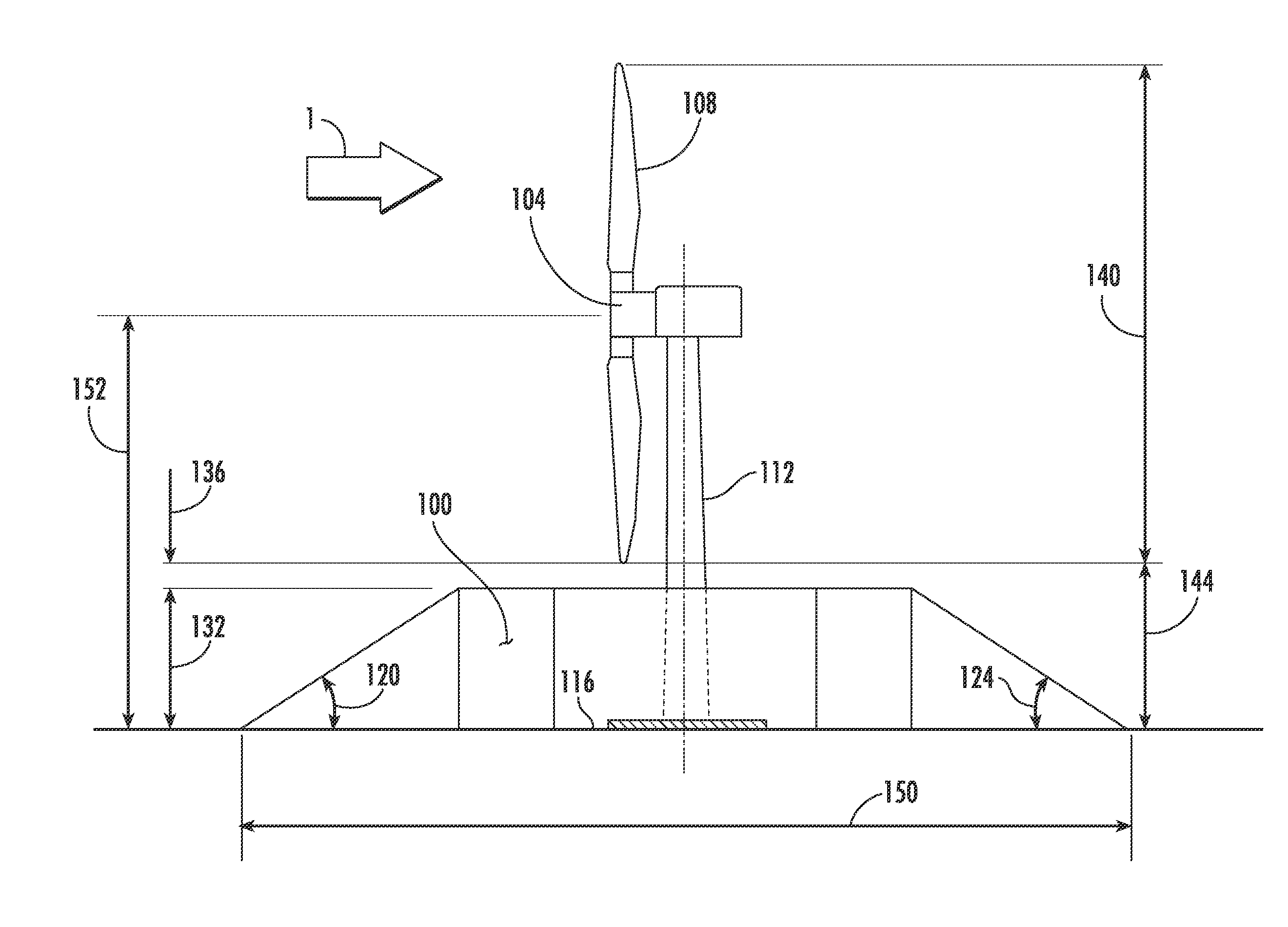
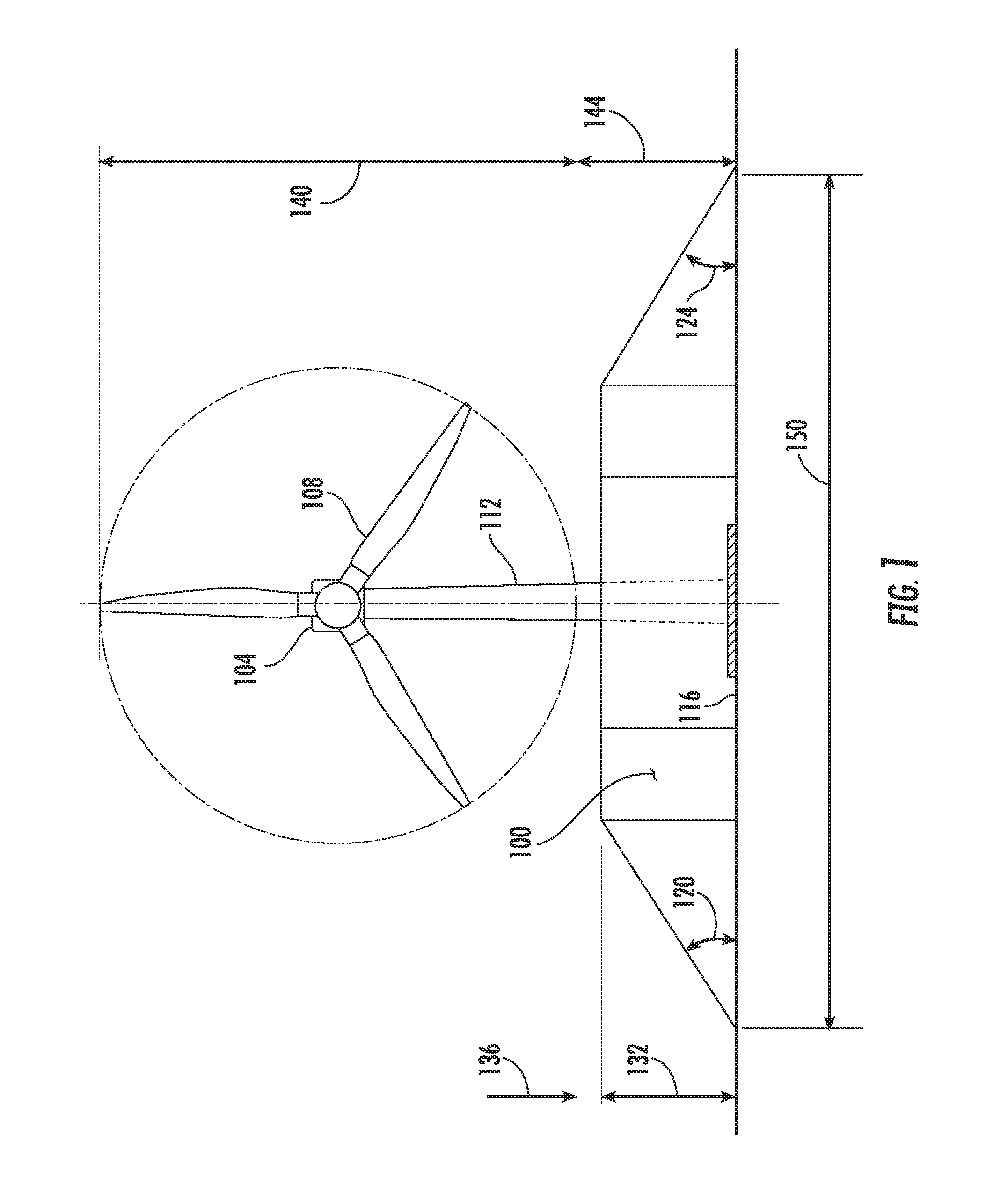
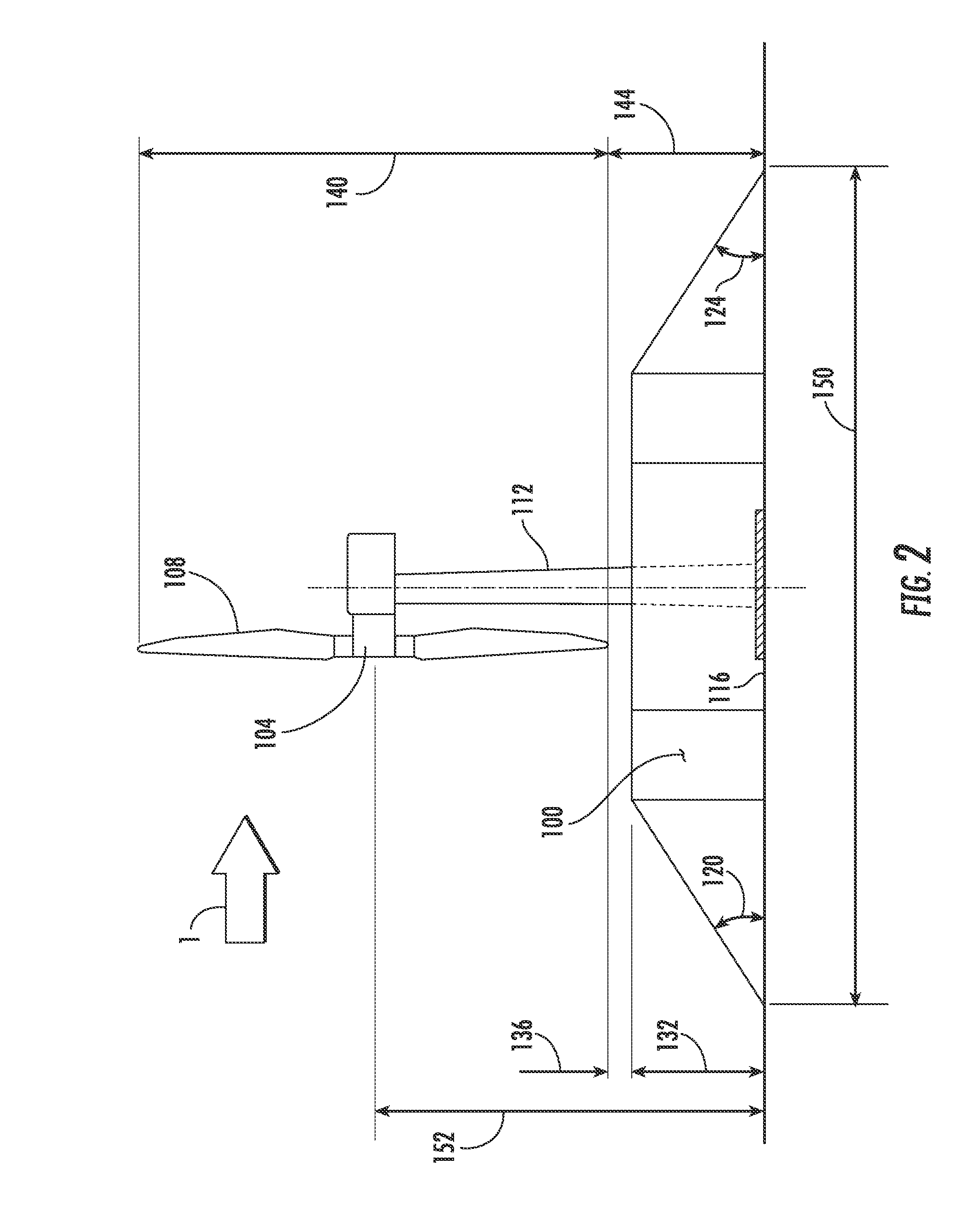
[0026]It is therefore an object to provide apparatuses and methods for the diversion of wind up to the rotor blades of a wind driven turbine to increase the wind speed of the available wind such that the increase in the wind speed impacting the rotor blades results in an increase in power generated by the wind driven turbine.

Problems solved by technology

As a result, the efficiency is reduced when the wind changes from the prevailing direction.
Although wind turbines are a well known method for harnessing wind energy, they suffer from several inherent disadvantages.
Additionally, wind turbines are only able to effectively extract energy from a circular cross section of the airstream.
A substantial portion of the airstream passes under, over, and around the area swept by the rotor, limiting its capacity to extract all of the power available from the surrounding wind.
Further, large scale wind turbines are only able to start operating in moderately high wind speeds of approximately 7 to 10 miles per hour (“MPH”).
This wind speed is not always available, which means that the wind turbine will sit idle and not be able to start operating until such time as the wind speed picks up and reaches the minimum threshold starting speed.
Another limiting factor for large scale wind turbines is that the current design is approaching maximum size.
Beyond a certain length, they are too long and too heavy to be self supporting.
However, few naturally occurring locations have the correct terrain to produce laminar airflow and to minimize air turbulence while at the same time maximizing the wind speed.
If such locations do exist, they often are facing the wrong direction to take advantage of the prevailing wind or are blocked when the wind shifts.
Lastly, even if the natural topography is suitable, the location may be too far away to economically tie a remotely located wind turbine into an existing power grid.
A further problem for small scale wind turbines, although ideally sized for some applications such as roof mounting on buildings, is that they are not as efficient as large sized turbines.
In addition, due to extreme turbulence at the building parapet and over the top of the building itself, small turbines are only able to produce limited amounts of power.
As a result, half of the turbine was shielded by the wall, thereby reducing its efficiency.
These types of augmentation devices used on wind turbine installations where the rotor turns into the direction of the wind have not proved very successful due to a variety of factors.
The main problem is that the opening of the diffuser needs to be exactly in line with the incoming wind.
In addition, it was found that even slight misalignment between the throat of the diffuser and the direction of the wind causes the air flow to go from laminar to turbulent, greatly reducing the efficiency.
This greatly complicates the design of the support tower and the yaw mechanism required to rotate both the diffuser and the rotor itself.
It was found on the turbines with built-in diffusers, that it is quite difficult to rotate the assembly fast enough to maintain the correct alignment.
An initial disadvantage is the requirement for reinforcement of the artificial mound to support the weight of the wind power generation apparatus on top of the artificial mound.
Engineering of this complexity would increase both the time of construction and cost of such a mound significantly.
Another disadvantage of the system disclosed in Boughton is that attempting to add a mound to already existing wind power generation emplacements would be even more costly in terms of engineering and construction due to the need to first remove the existing installation, build the mound, then reinstall the wind power generation unit.
The return on investment in such an installation based upon the increase in power generation sales would be so long as to render such a retrofit economically unfeasible.
An additional disadvantage of the prior art system as disclosed in Boughton is that the area from the top of the mound to the bottom of the blade of the wind generation turbine is open.

Method used


Image

  • Wind Diverter
  • Wind Diverter
  • Wind Diverter

Examples


Embodiment Construction

[0045]Current wind turbine design is based upon building the turbines as high as possible in order to raise the rotors as high as possible. Wind speeds are faster at higher elevations and current wind turbine designs seek to capture as much of these higher wind speeds as possible.

[0046]One of the limiting factors in current wind turbine design is the length of the rotor blades. Rotor blade length is restricted by the material of construction; i.e. aluminum, fiberglass or carbon fiber, to name a few. A limiting factor for the design of a wind turbine is that the maximum size of a rotor blade is dictated by the material of construction and current designs are reaching their maximum blade length for the materials of construction currently available. The total wind turbine height is therefore determined by the hub height plus the rotor blade length, with the rotor blade length restricted by the materials of construction available for use.

[0047]With these design parameters in mind, the r...


PUM


Abstract

Apparatuses and methods are provided for a wind diverter at least partially encircling a wind turbine support column to direct the wind from an area around a wind turbine to the rotor blades of the wind turbine. The wind diverter may also reduce turbulence and increases the laminar flow of the airstream delivered to the rotor blades. Additionally, the wind diverter increases both the volume of air and the velocity of the airstream reaching the rotor so as to increase the rotor speed. Increasing the rotor speed increases the energy available to the wind turbine. Energy increases as the cube of the rotor speed and the increased energy produces an increase in the power generated by the wind turbine. The wind diverter also allows a wind turbine to begin producing energy at lower initial wind speeds due to the concentration of air.

Description

CROSS-REFERENCE TO RELATED APPLICATIONS[0001]This application is related to and claims priority to U.S. Provisional Patent Application Ser. No. 61 / 056,486, filed on May 28, 2008, entitled “Wind Diverter,” the entire disclosure of which is incorporated by reference in its entirety.BACKGROUND OF THE INVENTION[0002]1. Technical Field[0003]The invention disclosed herein relates generally to power generation through the use of wind turbines, and more particularly to providing apparatuses and methods for diverting wind so as to increase the flow of wind supplied to the blades of a wind turbine and thus increasing the power generated by the action of the blades.[0004]2. Background Art[0005]The conversion of wind energy into electrical energy is well known. The most common apparatus for converting wind energy into useful power is the wind turbine which typically includes a plurality of blades directly exposed to the wind which are connected to a central hub and rotate about a common horizon...

Claims


Application Information

Patent Timeline
IPC IPC(8): F03D11/00
CPCF03D1/04Y02E10/72F05B2240/13Y02E10/728
Inventor BOYD, STEPHEN DAVID
Owner BOYD STEPHEN DAVID
Learn More