Illumination device and electro-optical apparatus
- Summary
- Abstract
- Description
- Claims
- Application Information
AI Technical Summary
Benefits of technology
Problems solved by technology
Method used
Image

Examples
first embodiment
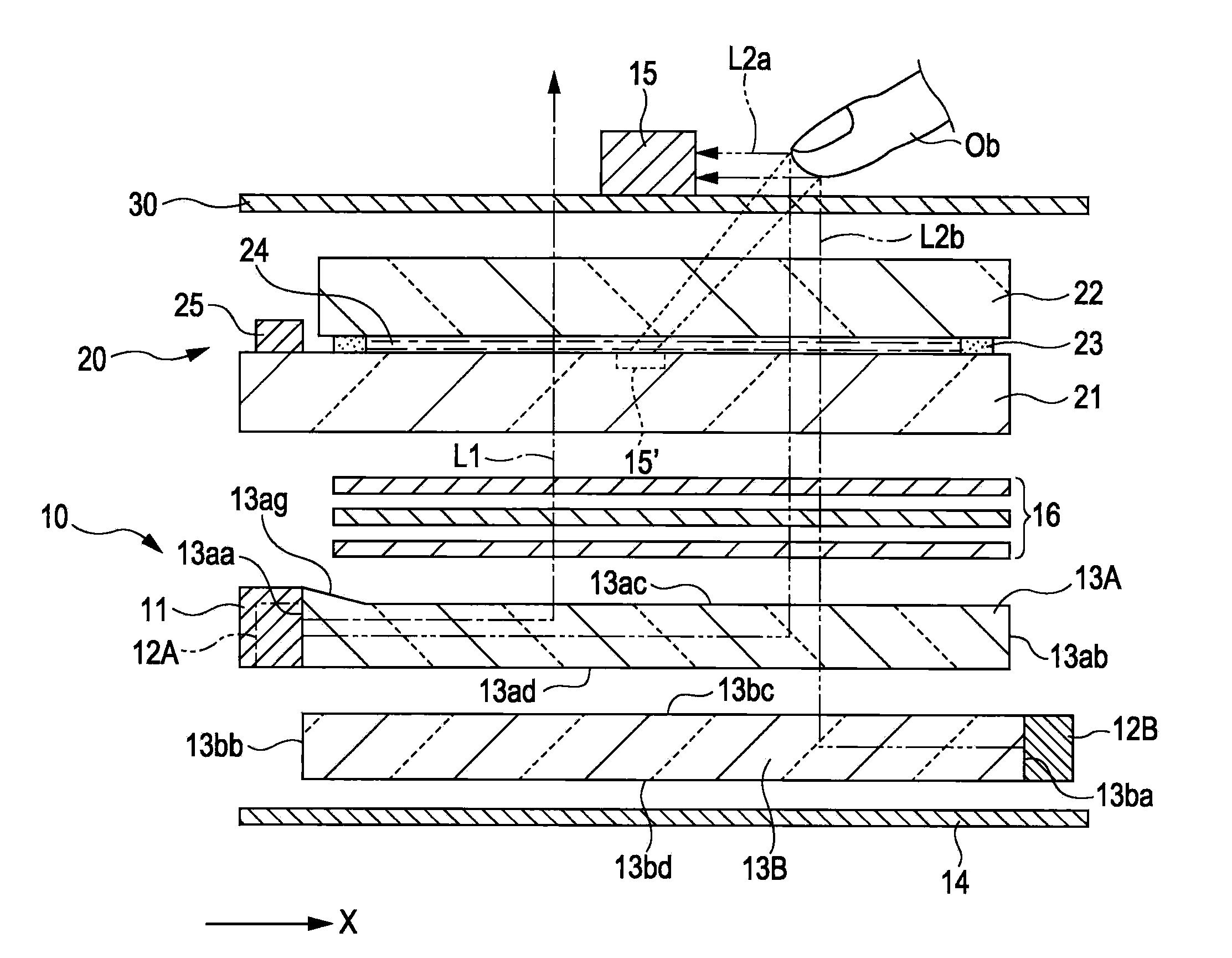
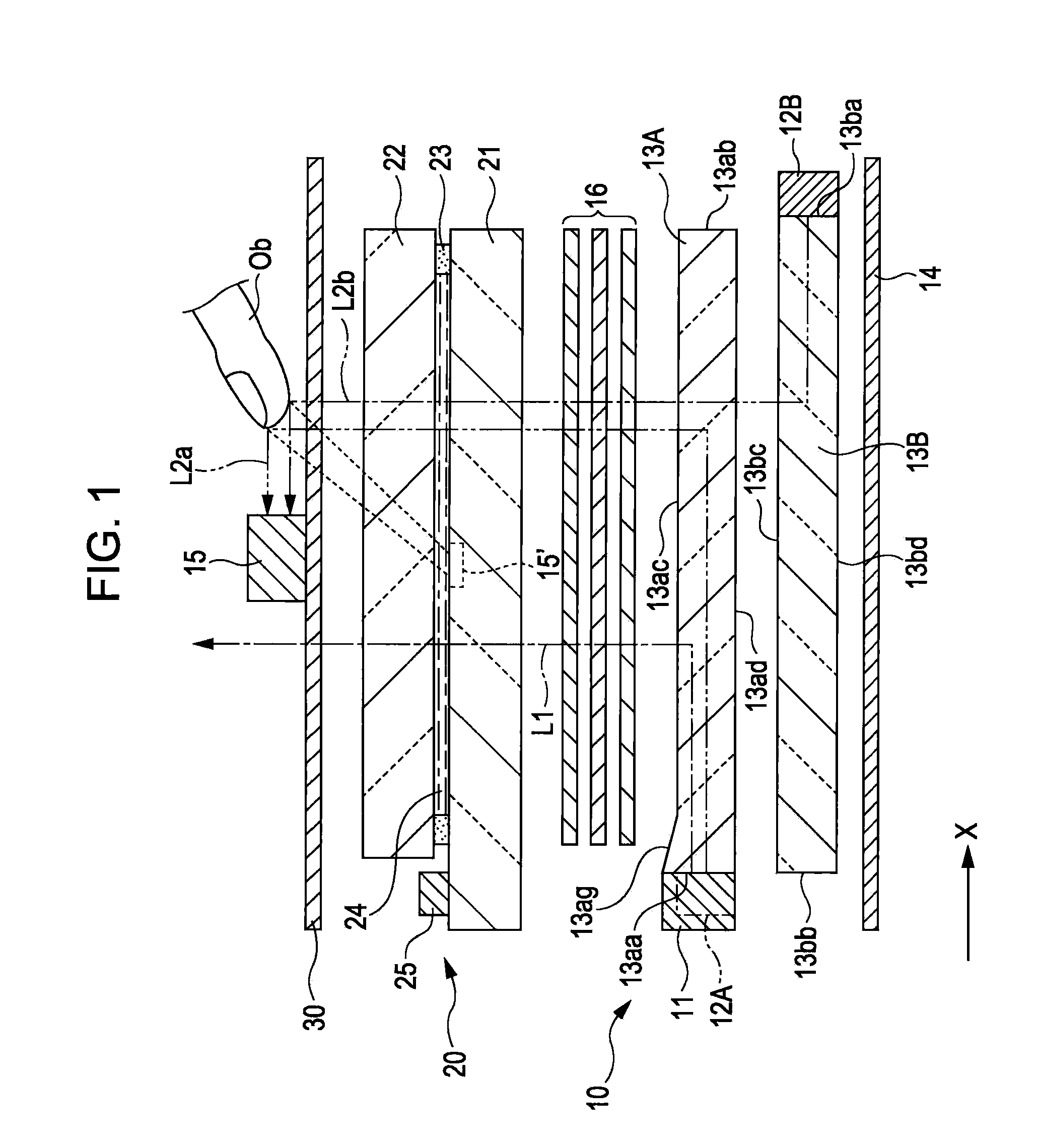
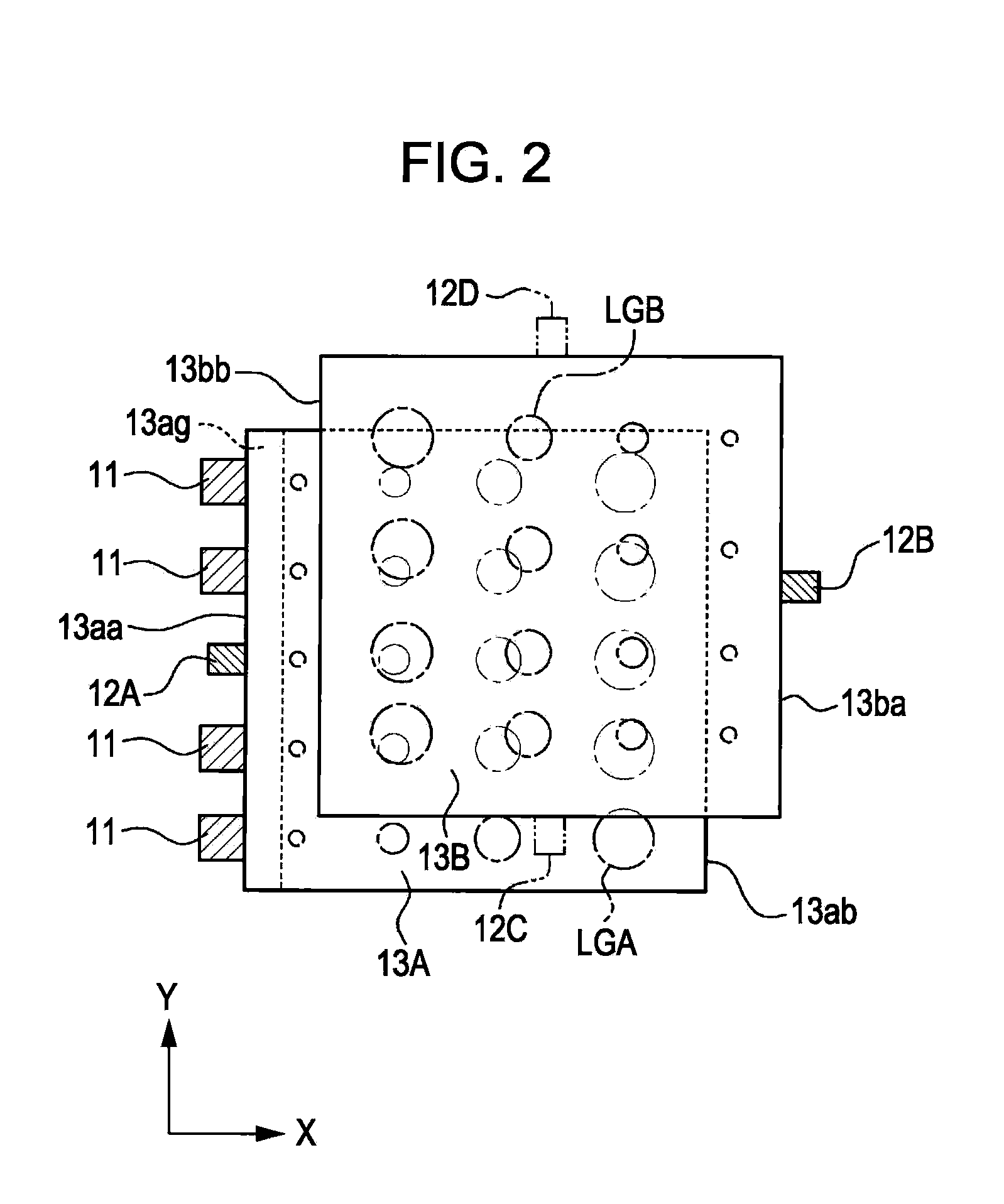
[0045]FIG. 1 is a simplified cross-sectional view schematically illustrating structure of an illumination device and an electro-optical apparatus according to a first embodiment of the invention, and FIG. 2 is a perspective view of a light source and a light guide plate according to the first embodiment, as viewed from a rear surface thereof.
[0046]An illumination device 10 according to the present embodiment is provided with an illumination light source 11 that emits an illumination light L1, position-detecting light sources 12A and 12B that emit position detecting lights L2a and L2b, respectively, a first light guide plate 13A and a second light guide plate 13B on which these lights are incident, a reflecting plate 14 that is disposed at the back of the light guide plates 13A and 13B, and a photodetector 15 that is disposed on an emitting side from which the position detecting lights are emitted. The light guide plates 13A and 13B are formed of a transparent light guiding material ...
second embodiment
[0070]Next, a second embodiment of the invention will be described with reference to FIGS. 3 and 4. FIG. 3 is a simplified cross-sectional view schematically illustrating an illumination device and an electro-optical apparatus according to a second embodiment of the present invention, and FIG. 4 is a perspective view of a light source and a light guide plate according to the second embodiment, as viewed from a rear surface thereof.
[0071]In this embodiment, the same portions as those of the above-described first embodiment will be denoted by the same reference numerals, and descriptions thereof will be omitted. The present embodiment is different from the first embodiment in that the illumination light source 11 is disposed so as to oppose the second light incident surface 13ba of the second light guide plate 13B of the first embodiment. That is, in the present embodiment, the illumination light L1 emitted from the illumination light source 11 is incident to the first light guide pla...
third embodiment
[0072]Next, a third embodiment of the invention will be described with reference to FIGS. 5 and 6. FIG. 5 is a simplified cross-sectional view schematically illustrating an illumination device and an electro-optical apparatus according to a third embodiment of the present invention, and FIG. 6 is a perspective view of a light source and a light guide plate according to the third embodiment, as viewed from a rear surface thereof.
[0073]In this embodiment, the same portions as those of the above-described second embodiment will be denoted by the same reference numerals, and descriptions thereof will be omitted. Although the present embodiment is similar to the second embodiment in that the same light guide plates 13A′ and 13B′ as those used in the second embodiment are provided, they are different in that one is an illuminating light guide plate 13A′ and the other is a position-detecting light guide plate 13B′. Moreover, the illumination light source 11 is disposed so as to oppose the ...
PUM
 Abstract
Description
Claims
Application Information
 - R&D
- Intellectual Property
- Life Sciences
- Materials
- Tech Scout
- Unparalleled Data Quality
- Higher Quality Content
- 60% Fewer Hallucinations
Browse by: Latest US Patents, China's latest patents, Technical Efficacy Thesaurus, Application Domain, Technology Topic, Popular Technical Reports.
© 2025 PatSnap. All rights reserved.Legal|Privacy policy|Modern Slavery Act Transparency Statement|Sitemap|About US| Contact US: help@patsnap.com