
Thermoelectric Generator for Implants and Embedded Devices

a technology of thermoelectric generators and embedded devices, which is applied in the direction of thermoelectric devices with peltier/seeback effect, electrotherapy, etc., can solve the problems of limited lifetime of batteries, insufficient power generated by tegs based on such small temperature differences, and achieve the effect of increasing the temperature difference available and reliably powering an implanted or embedded devi

Inactive Publication Date: 2009-11-26
STICHTING IMEC NEDERLAND
View PDF10 Cites 28 Cited by
  • Summary
  • Abstract
  • Description
  • Claims
  • Application Information

AI Technical Summary

Benefits of technology

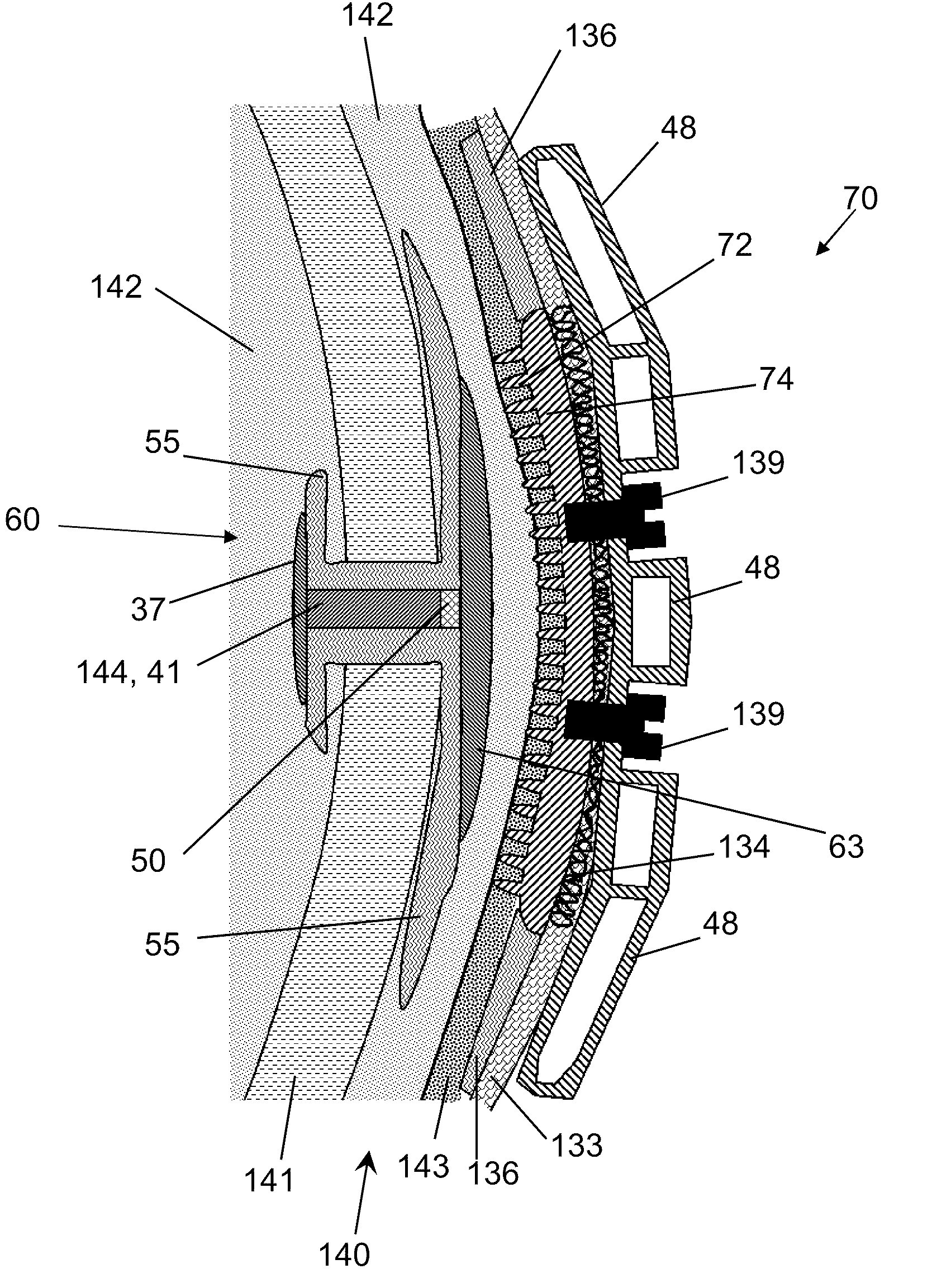
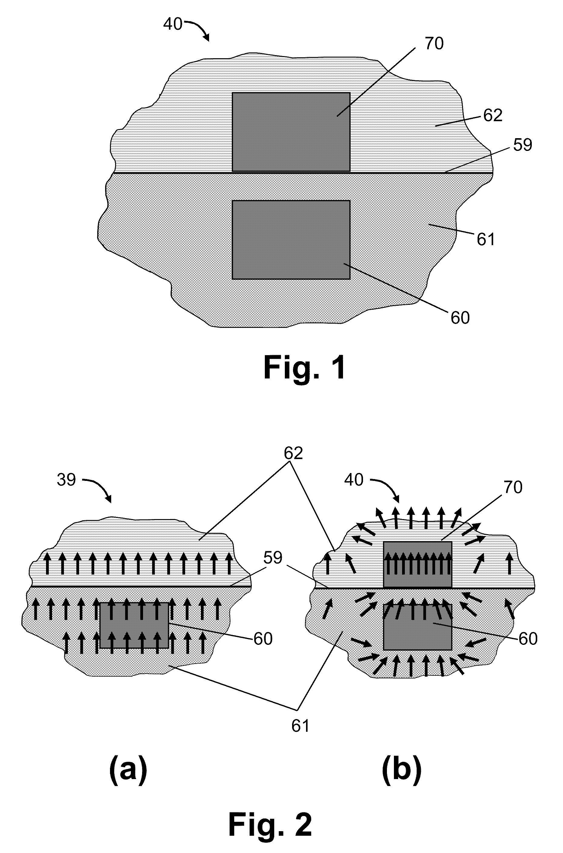
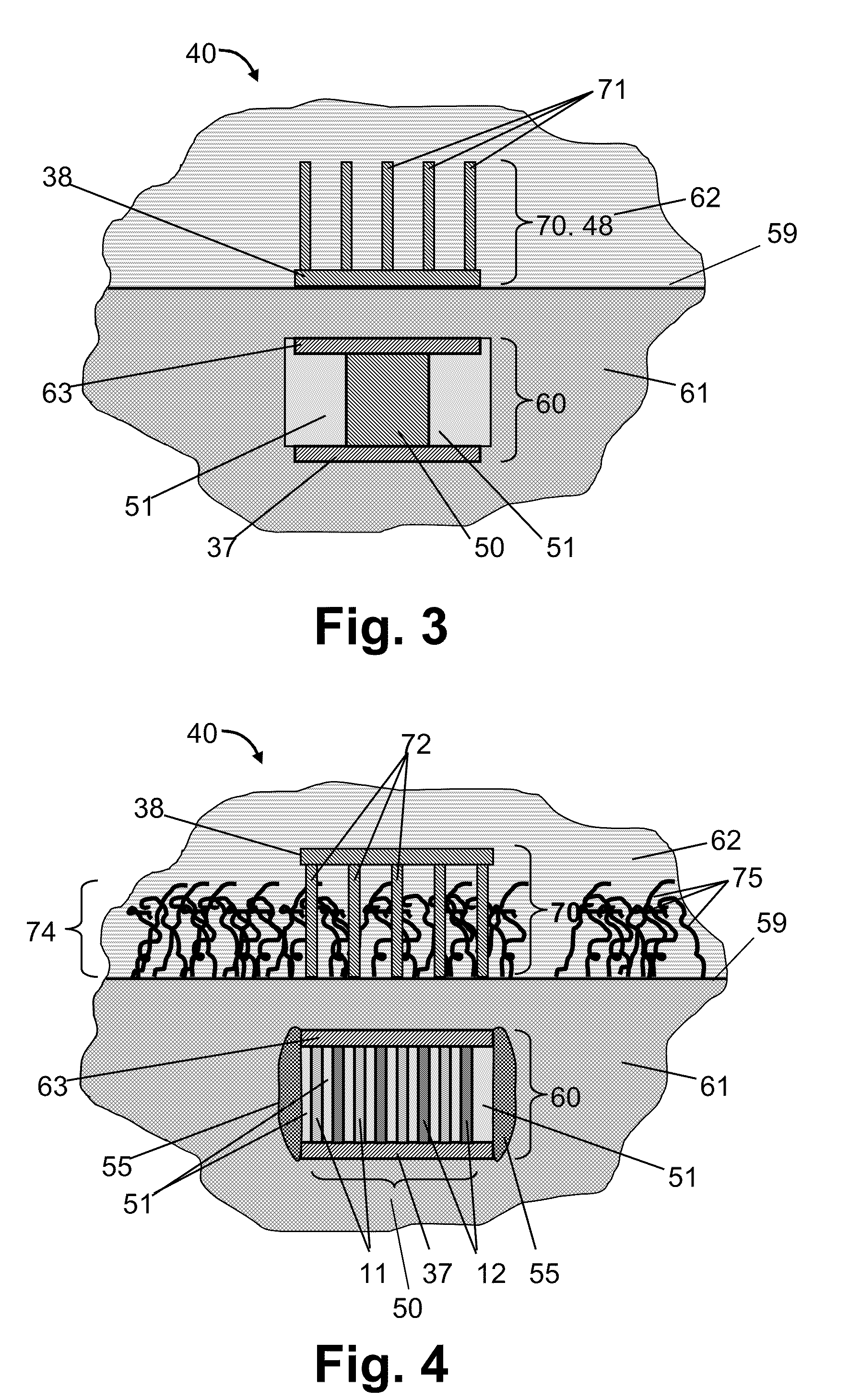
[0007]Both the implantable or embeddable unit and the wearable or external unit can be designed such that a natural heat flow, e.g. a heat flow resulting from heat produced in the human or animal body or inside a mechanical structure, is directed more efficiently into the thermopile unit. This can lead to a higher power generation as compared to prior art implantable TEGs.
[0011]The present invention can result in a number of advantages. For example, certain embodiments of the invention provide a TEG that is able to reliably power an implanted or embedded device. Similarly, certain embodiments of the present invention increase the temperature differences available inside the human or animal body and to provide a TEG that is suitable for using such temperature differences to generate electricity.

Problems solved by technology

All of these devices require a power source, such as a battery, which has a limited lifetime.
This small temperature difference is usually less than 1° C., which is often too small to allow the generated thermoelectric power to completely power many types of implantable medical device.
Therefore, the power that can be generated by a TEG based on such small temperature differences may be insufficient for reliably powering an implanted device, and regular replacement of an implanted battery may still be needed, as e.g. described in U.S. Pat. No. 6,640,137.

Method used


Image

  • Thermoelectric Generator for Implants and Embedded Devices
  • Thermoelectric Generator for Implants and Embedded Devices
  • Thermoelectric Generator for Implants and Embedded Devices

Examples


Embodiment Construction

[0025]In the following detailed description, numerous specific details are set forth in order to provide a thorough understanding of the invention and how it may be practiced in particular embodiments. However it will be understood that in some embodiments the present invention may be practiced without conforming with these specific details. In other instances, well-known methods, procedures and techniques have not been described in detail, so as not to obscure the present invention. While certain aspects of the present invention will be described with respect to particular embodiments and with reference to certain drawings, the invention is not to be limited thereto. The drawings included and described herein are schematic and are not meant to limit the scope of the invention. It is also noted that in the drawings, the size of some elements may be exaggerated and, therefore, not drawn to scale for illustrative purposes.

[0026]Furthermore, the terms first, second and the like in the ...


PUM


Abstract

The present invention provides a TEG device comprising a first unit comprising a thermopile unit and a second unit comprising a cold plate and / or a radiator. One of the first and second units is adapted for being embedded or implanted into a body, while the other of the first and second units is adapted for being placed at the outer surface of the body, i.e. in a fluid. The first and second units are adapted for being thermally connected to each other through the surface between the body and the fluid when in use.

Description

CROSS-REFERENCE TO RELATED APPLICATIONS[0001]This application claims priority under 35 U.S.C. 119(e) to U.S. Provisional Patent Application Ser. No. 61 / 055,162, filed May 22, 2008, which is hereby incorporated herein by reference in its entirety.FIELD OF THE INVENTION[0002]The present invention relates to power supplies and to thermoelectric generators (TEGs) and more particularly to TEGs comprising an implantable or embedded unit and a wearable or external unit. The TEGs of the present invention can be used, for example, for powering embedded devices or implanted devices, for example devices implanted in the body of an endotherm such as a human being or an animal, or devices embedded in mechanical structures like tubes or pipes.BACKGROUND OF THE INVENTION[0003]A thermoelectric generator utilises a temperature difference occurring between a hot (warm) object, i.e. a heat source, and its colder surroundings, i.e. a heat sink, or vice versa, and can be used to transform a consequent h...

Claims


Application Information

Patent Timeline
Patent Type & Authority Applications(United States)
IPC IPC(8): A61N1/00H10N10/13
CPCH01L35/30A61N1/08H10N10/13
Inventor LEONOV, VLADIMIR
Owner STICHTING IMEC NEDERLAND
Learn More