
Rotational coupling device with sealed key

a technology of rotating coupling and sealing key, which is applied in the direction of mechanical actuated clutches, hose connections, interengaging clutches, etc., can solve the problem that the sealing key is subject to possible damage, and achieve the effect of less likely damag

Inactive Publication Date: 2009-11-26
WARNER ELECTRIC TECH
View PDF9 Cites 8 Cited by
  • Summary
  • Abstract
  • Description
  • Claims
  • Application Information

AI Technical Summary

Benefits of technology

[0008]A rotational coupling device in accordance with the present invention represents an improvement over conventional devices. By locating the seals in the key, the seals may be removed and replaced without removing the coupling device from the shaft. Further, the seals are less likely to be damaged during assembly of the device on the shaft.

Problems solved by technology

First, removal and replacement of the seals requires disassembly of the coupling device from the shaft.
Second, the seals are subject to possible damage as the coupling device is installed on the shaft.

Method used


Image

  • Rotational coupling device with sealed key
  • Rotational coupling device with sealed key
  • Rotational coupling device with sealed key

Examples


Embodiment Construction

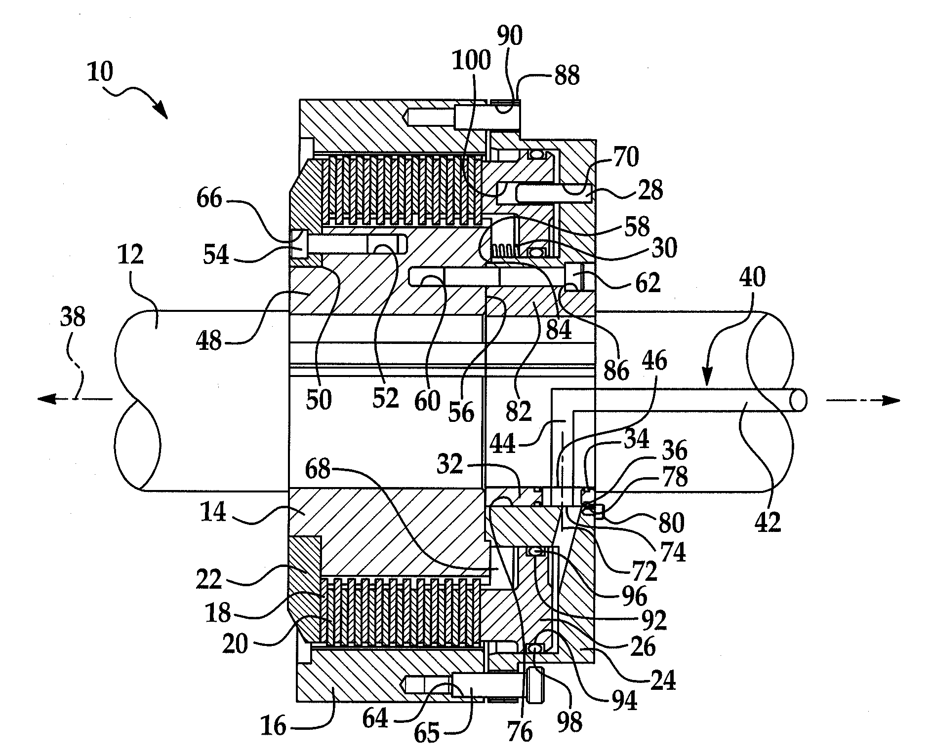
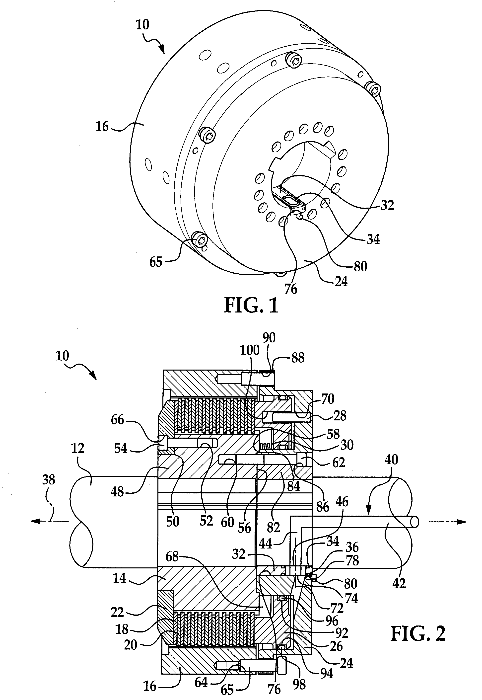
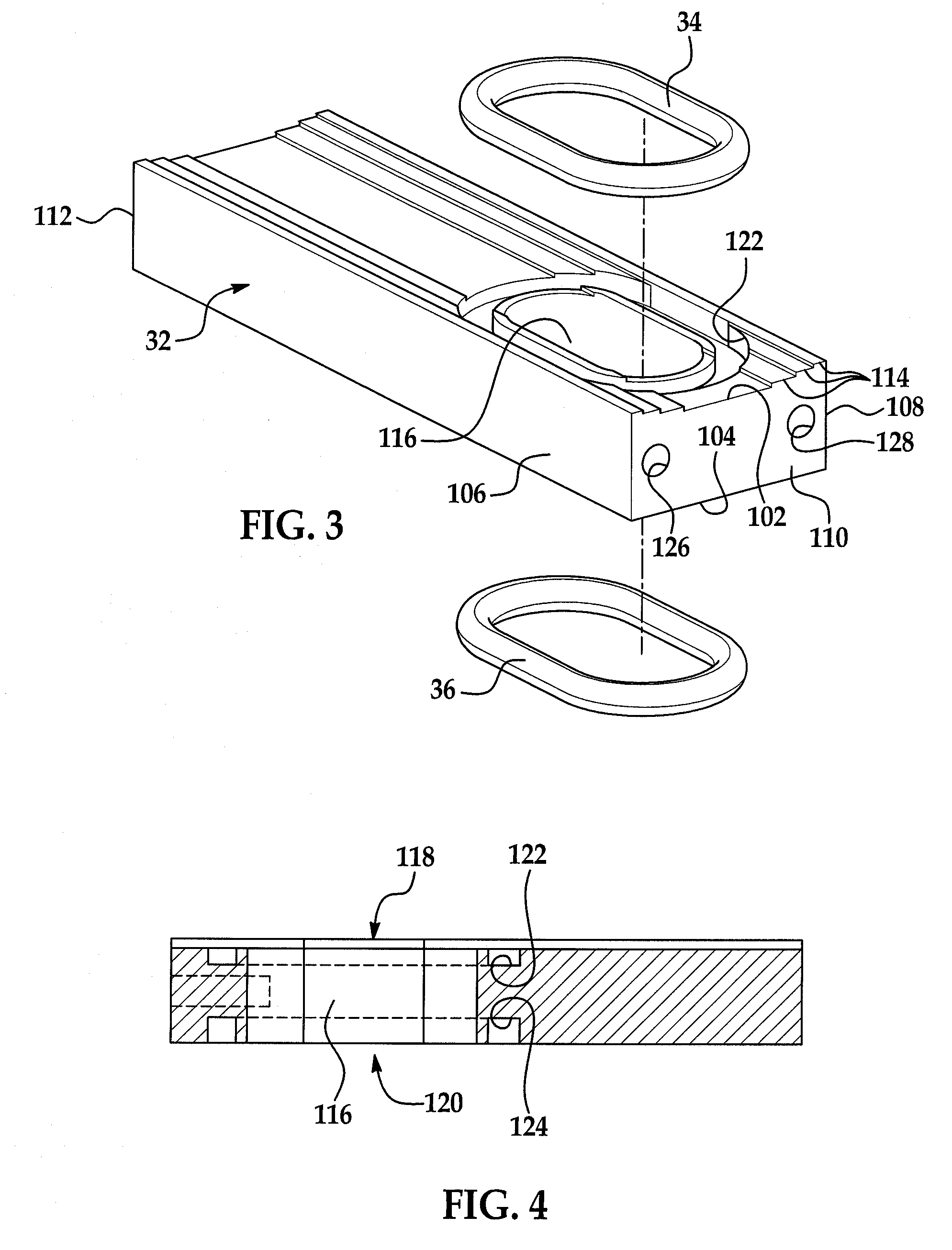
[0014]Referring now to the drawings wherein like reference numerals are used to identify identical components in the various views, FIGS. 1-2 illustrate a rotational coupling device 10 in accordance with the present invention. Device 10 functions as a clutch or brake to transfer torque between rotational bodies. In the illustrated embodiment, device 10 functions as a clutch to transfer torque from a driving shaft 12 (see FIG. 2) to a rotating body (not shown) such as a driven shaft. Device 10 may include a hub 14, a ring 16, friction discs 18, 20, a back plate 22, a housing 24, a piston 26, dowels 28, springs 30, a key 32, and seals 34, 36.

[0015]Referring to FIG. 2, device 10 is configured to be received on, and to control torque transfer to or from, shaft 12. Shaft 12 is disposed about a rotational axis 38. Shaft 12 defines a fluid passageway 40 through which pneumatic and / or hydraulic fluid may be provided to device 10. The fluid passageway 40 may include an axially extending pass...


PUM


Abstract

A fluid actuated rotational coupling device is provided with improved sealing of fluid passages. The device includes a fluid actuated rotational coupling that is disposed on a rotatable shaft. The coupling defines a fluid port. A key is received within a keyway in the coupling and / or shaft and defines a fluid passage extending therethrough having fluid ports at either end aligned with the fluid port in the coupling and a fluid port in the shaft. The key also defines grooves formed in surfaces of the key and surrounding the fluid ports. Seals are disposed within the grooves in the key. By locating the fluid passage and seals in the key, the seals may be removed and replaced without removing the coupling from the shaft. Further, the seals are less likely to be damaged during installation of the coupling device on the shaft.

Description

BACKGROUND OF THE INVENTION[0001]1. Field of the Invention[0002]This invention relates to rotational coupling devices such as brakes and clutches and, in particular, to a fluid-actuated rotational coupling device in which fluid is provided from a shaft to the coupling through a sealed key.[0003]2. Discussion of Related Art[0004]Rotational coupling devices such as clutches and brakes are used to control transfer of torque between rotational bodies such as rotatable shafts. Conventional coupling devices can be actuated in a variety of ways including through electromagnetic actuation and fluid actuation. In fluid actuated devices, fluid may be provided to the device through hoses connected to fluid ports. Alternatively, fluid may be provided to the device through fluid passageways in a shaft on which the device is mounted. In the latter case, the fluid connection between the shaft and coupling device must be sealed. In conventional systems, grooves have been machined in the shaft or an...

Claims


Application Information

Patent Timeline
Patent Type & Authority Applications(United States)
IPC IPC(8): F16L17/00
CPCF16D2048/0212F16D25/0638
Inventor BLUHM, BRENTON CHARLES
Owner WARNER ELECTRIC TECH
Learn More