Connector

Active Publication Date: 2021-03-18
SUMITOMO WIRING SYST LTD
View PDF0 Cites 0 Cited by
  • Summary
  • Abstract
  • Description
  • Claims
  • Application Information

AI Technical Summary

Benefits of technology

The patent is about a connector assembly that reduces the number of components and prevents damage to the wire. The connector includes a housing and a retainer that hold the wire. A push-in piece on the housing pushes a deflecting piece on the retainer into the outer surface of the wire, expanding its diameter in a different direction than the push-in direction. A fixing piece on the retainer prevents the wire from expanding further. A lance on the deflecting piece pushes the wire at a later time, reducing the likelihood of damage. Overall, this configuration reduces the risk of damage and simplifies the assembly process.

Problems solved by technology

The, cost increases with the number of components.
Further, if an attempt is made to assemble the retainer with the housing while the deflecting piece is pushed into the outer peripheral surface of the wire, the wire may be damaged, such as by the biting of the deflecting piece and the fixing piece into a coating of the wire.

Method used


Image

  • Connector
  • Connector
  • Connector

Examples


Embodiment Construction

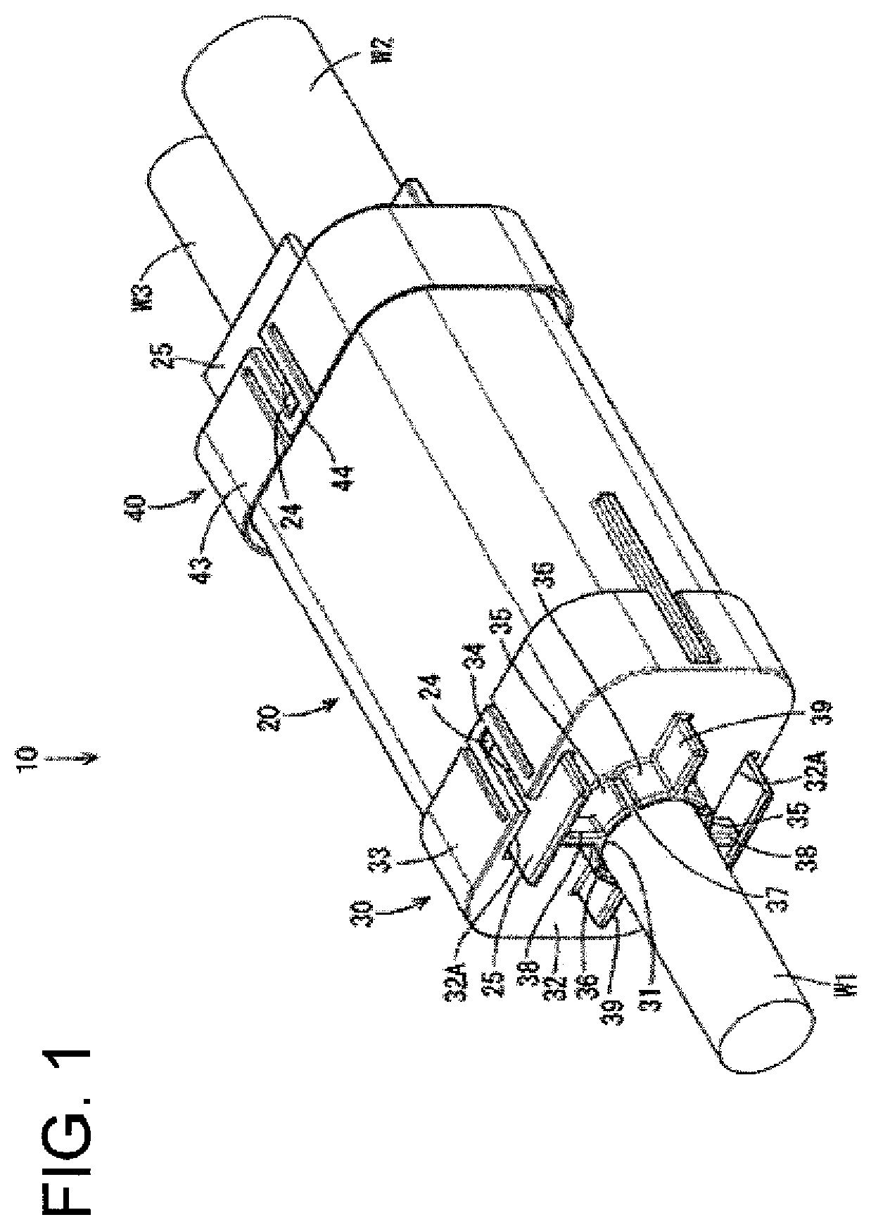
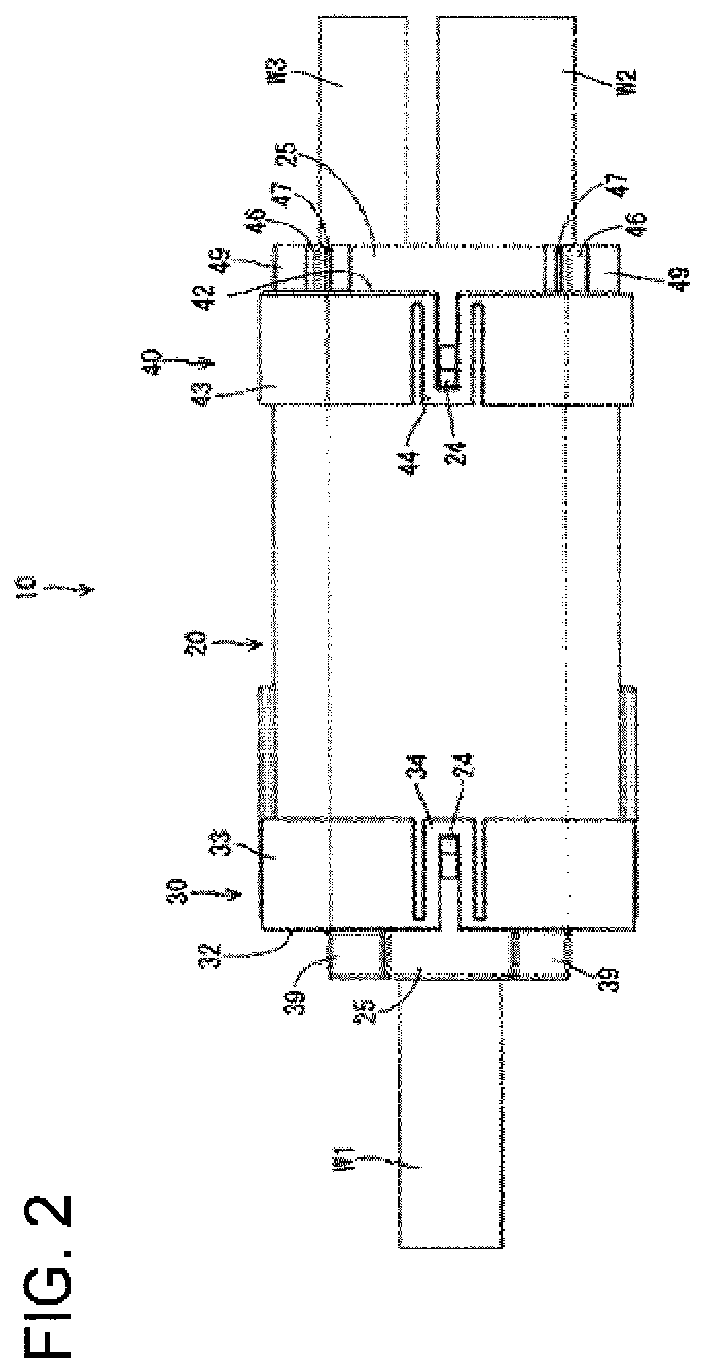
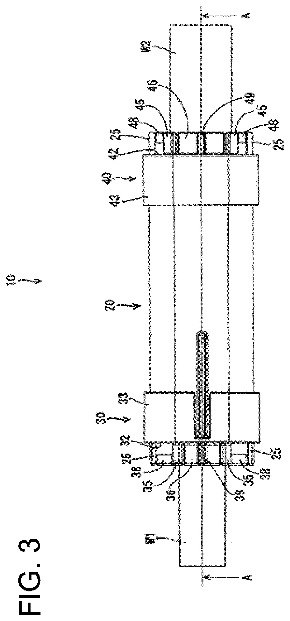
[0028]An embodiment is described with reference to FIGS. 1 to 16. A connector 10 of this embodiment includes a housing 20 extending in a front-rear direction, front and rear retainers 30, 40 mounted on both front and rear parts of the housing 20, a first wire W1 pulled out forwardly from the first retainer 30 on a front side and a second wire W2 and a third wire W3 pulled out rearwardly from the second retainer 40 on a rear side, as shown in FIG. 1. As shown in FIG. 2, the first wire W1 is smaller in diameter than the second wire W2 and larger in diameter than the third wire W3. A current input from the second wire W2 is branched and output to the first and third wires W1, W3.

[0029]As shown in FIG. 4, a cavity 21 penetrates the housing 20 in the front-rear direction. A conductive member 50 for conductively connecting cores of the wires W1, W2 and W3 is accommodated in the cavity 21. The cores of the wires W1, W2 and W3 are connected to the conductive member 50, for example, by resis...


PUM


Abstract

A connector (10) has a wire, a rubber plug (60) fit on an outer surface of the wire and a housing 20 including a forwardly-open plug accommodating portion (22). The rubber plug (60) is sandwiched between an inner peripheral surface of the plug accommodating portion (22) and the outer surface of the wire. A retainer holds the rubber plug 60 in the plug accommodating portion (22) by being mounted on the plug accommodating portion (22) from the front. The retainer includes deflecting pieces (35) relatively displaceable with respect to the outer surface of the wire and fixing pieces (36) relatively undisplaceable with respect to the wire. The housing (20) includes push-in pieces (25) for pushing the deflecting pieces (35) into the outer surface of the wire. The wire is held in the retainer by the deflecting pieces (35) pushed into the surface of the wire and the fixing pieces (36).

Description

BACKGROUNDField of the Invention[0001]This specification relates to a connector.Related Art[0002]Japanese Unexamined Patent Application Publication No. 2012-511804 discloses a shield connector with a strain relief mechanism. This connector assembly includes an inner housing assembly, an outer housing assembly, a spacer, a cable seal, a collet and a retainer. The cable seal seals against the intrusion of moisture and other foreign matter into the outer housing assembly through the rear end of the outer housing assembly. The collet fixes the cable to ensure that a tension from the cable does not act on the connection of the cable seal and a shield. The collet includes a finger-like portion to be pushed into the cable. If the retainer is assembled with the outer housing assembly from behind the collet, a push-in portion of the retainer pushes the finger-like portion of the collet so that the cable can be fixed to the collet.[0003]However, the cable of the above-described connector asse...

Claims


Application Information

Patent Timeline
IPC IPC(8): H01R13/58H01R13/52
CPCH01R13/5812H01R13/5208H01R31/02
Inventor KAMEMURA, MASATO
Owner SUMITOMO WIRING SYST LTD
Why Eureka
Try Eureka