
Display apparatus and navigation device

a technology for navigation devices and display devices, applied in static indicating devices, navigation instruments, instruments, etc., can solve problems such as troublesome operation and complicated construction, and achieve the effect of flexible handling of images

Inactive Publication Date: 2009-11-19
PANASONIC CORP
View PDF8 Cites 27 Cited by
  • Summary
  • Abstract
  • Description
  • Claims
  • Application Information

AI Technical Summary

Benefits of technology

[0043]According to the present invention, one of the first and second images is handled by the remote control information inputting unit and the other of the first and second image is handled by the touch operation information inputting unit, and the specification unit indicating targets of the images is provided. Thus, the operator can handle the images flexibly. Neither increasing required operation nor providing a sensor or the like for detecting a position of the remote control information inputting unit is needed.

Problems solved by technology

However, in the display apparatus of Document 2, since the driver or the fellow passenger must reach his / her hand to the specified touch area, and then instruct which of them the input comes from beforehand, the operation is troublesome.
Thus, the construction must be complicated.

Method used


Image

  • Display apparatus and navigation device
  • Display apparatus and navigation device
  • Display apparatus and navigation device

Examples


embodiment 1

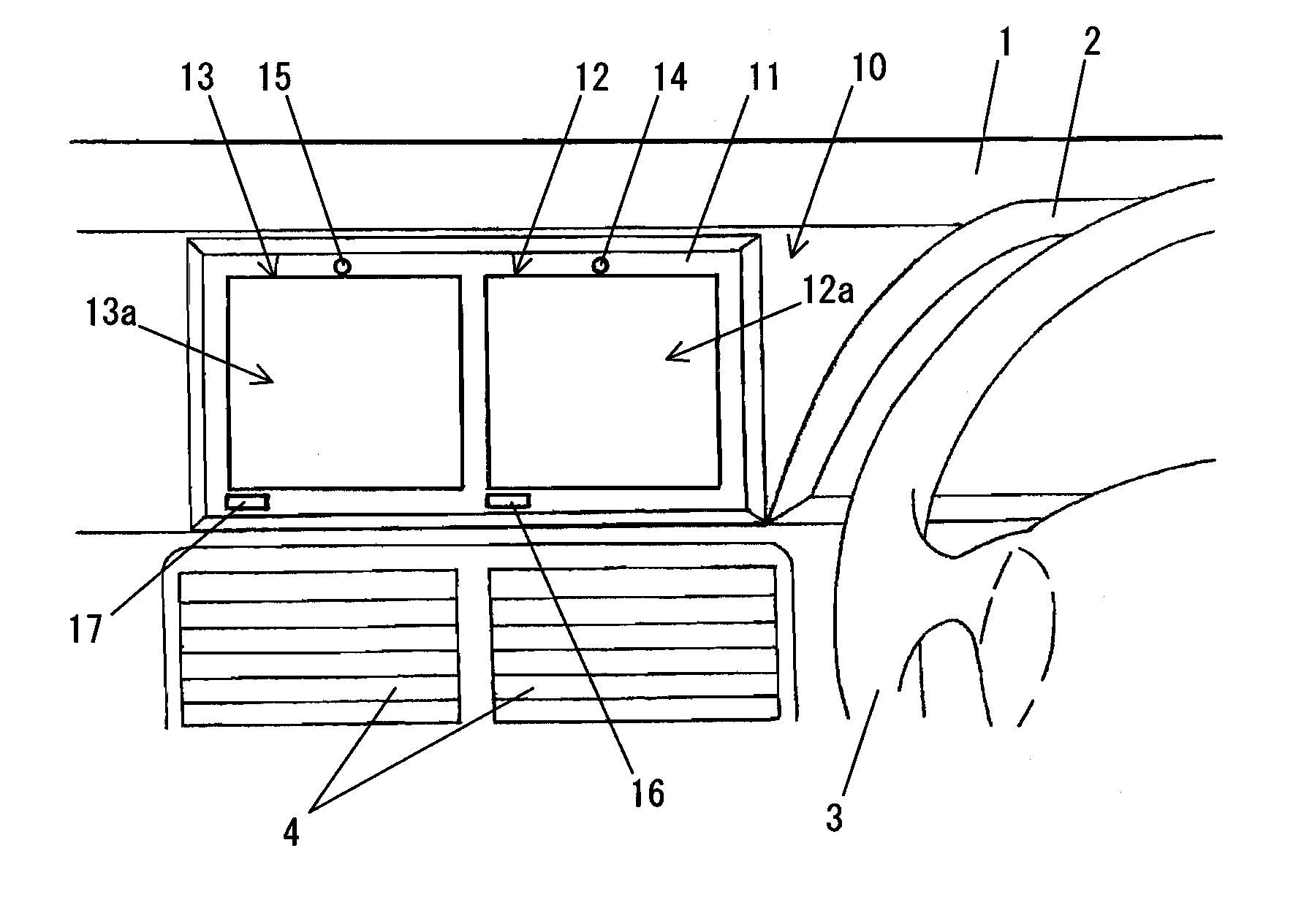
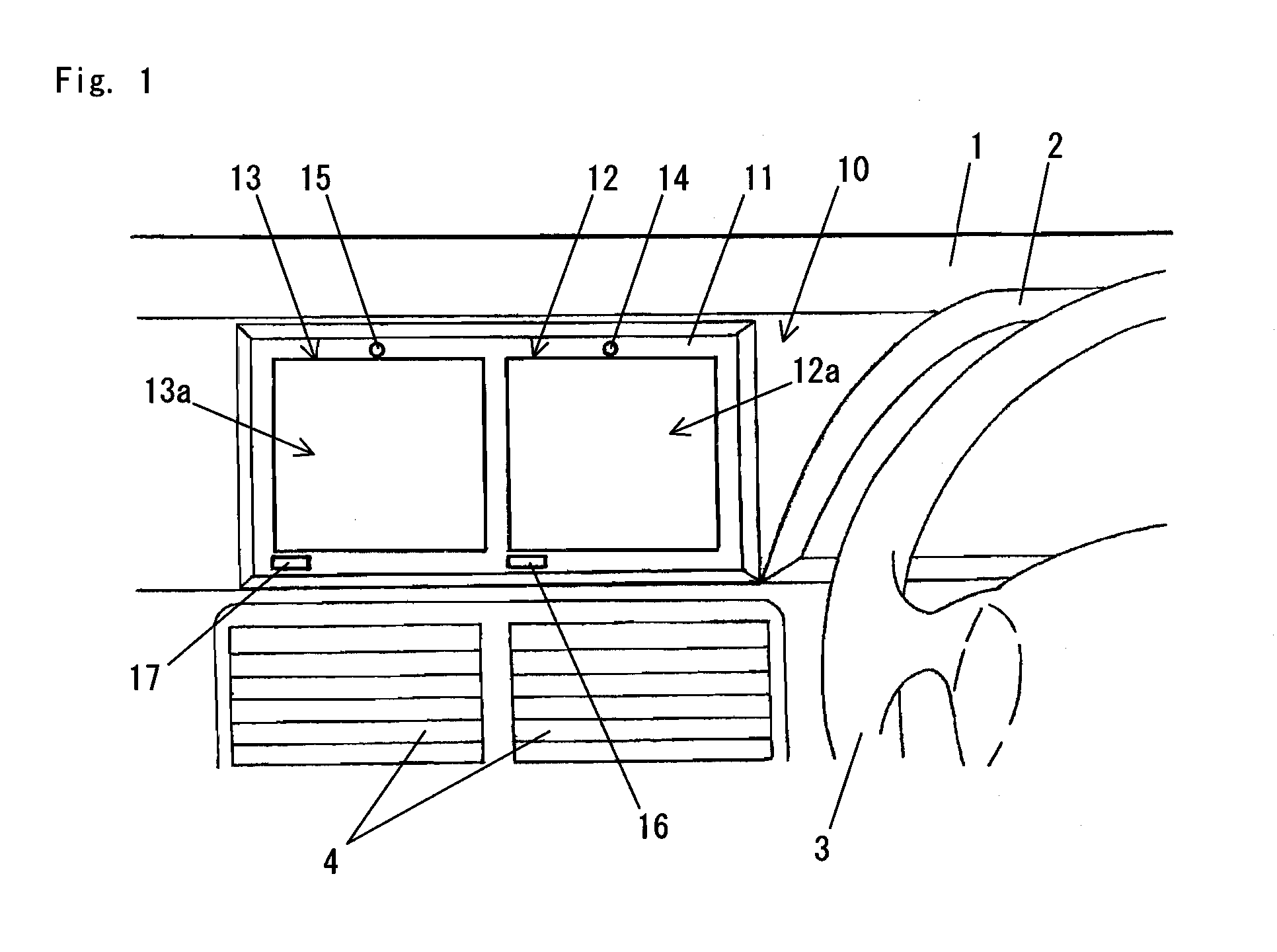
[0128]FIG. 1 illustrates a view showing an area near a dashboard of a car with which a display apparatus in Embodiment 1 of the present invention is equipped. The display apparatus of the present embodiment is preferably used as a display of a car navigation device, and has been built in a car before the car is delivered to a user.

[0129]As shown in FIG. 1, a center console 2 including an instrument panel is arranged in a dashboard 1 located in front of the driver's seat. A steering wheel 3 is provided in the side of the driver's seat of the center console 2. Furthermore, an air conditioner outlet 4, which sends fresh, cold, or warm air to the driver and the fellow passenger, is arranged in the center of the dashboard 1.

[0130]A display apparatus 10 of the present embodiment is preferably built in the dashboard 1 at a portion, where the driver's field of view is not interrupted, above the air conditioner outlet 4. A frame 11 is fixed on the dashboard 1, thereby the display apparatus 1...

embodiment 2

[0146]FIG. 4 illustrates a view showing an area near a dashboard of a car with which a display apparatus in Embodiment 2 of the present invention is equipped. The display apparatus of the present embodiment is preferably used as a display of a car navigation device, and belongs to a type in which the device is installed after delivery of the car. In FIG. 4, the same symbols are given to elements each having the same function as elements of FIG. 1 in order to omit explanation.

[0147]As shown in FIG. 4, the display apparatus of the present embodiment has the different configuration of and so on the frame from Embodiment 1. In the present embodiment, the display apparatus is installed in the car by fixing a mounting plate 20, which is provided at the bottom, to a central portion of a top panel 1a of the dashboard 1. A cylindrical column 21 is provided in the vertically upward direction from the central portion of the mounting plate 20.

[0148]Boss portions 22a and 23a are formed in a firs...

embodiments 1 and 2

Details of Embodiments 1 and 2

[0153]Next, referring to FIG. 6, the details of Embodiments 1 and 2 are explained. Embodiments 1 and 2 are fundamentally the same in a block diagram level and a flow chart level. Moreover, in FIG. 6, the same symbols are given to elements each having the same function as elements of FIGS. 1 to 5 in order to omit explanation.

[0154]FIG. 6 is a block diagram of a car navigation device in Embodiments 1 and 2 of the present invention. This car navigation device includes a source supplying unit 40, the display apparatus 10, and other elements.

[0155]Within the source supplying unit 40, a hard disk drive 45 stores AV reproduction information as shown in the left side of FIG. 8, and outputs the AV reproduction information according to the predetermined format (a method which can be reproduced by the display apparatus 10) to a selector 56 of the display apparatus 10.

[0156]When a DVD (Digital Versatile Disk) 46 is set, a DVD player 47 reproduces the reproduction i...


PUM


Abstract

A display apparatus operable to flexibly perform display control to a plurality of images is provided, when the plurality of images are displayed on the display apparatus, and each image is selected either as a touch operation target or as a remote control target alternatively. The display apparatus comprises: a first display device 12 and a second display device 13 operable to display a first image and a second image simultaneously; a CPU 51 operable to decide either the first image or the second image to be displayed as a remote control target and the other one as a touch operation target; a remote controller 32 operable to accept a control operation input regarding an image to be a remote control target between the first image and the second image; a first touch panel 12a and a second touch panel 13a operable to accept a touch operation input regarding an image to be a touch operation target between the first image and the second image; and a first LED 14 and a second LED 15 operable to indicate that the first image and the second image are either a remote control target or a touch operation target.

Description

TECHNICAL FIELD[0001]The present invention relates to a display apparatus operable to display a first image and a second image, and a navigation device including the display apparatus. Especially, the present invention relates to a technology of operating a plurality of display apparatuses or a dual view display (a display device operable to simultaneously display two different images according to viewing angles) by a remote controller or a touch panel alternatively.BACKGROUND ART[0002]Document 1 (Published Japanese patent application 2001-280979) discloses providing two display devices as the display apparatus of the navigation device installed in a car, enlarging a display area, and displaying different images on each of the display devices, respectively.[0003]Moreover, a dual view display, which is a single display device and operable to display different images for a driver and a fellow passenger sitting in the front passenger seat (he / she is called as a fellow passenger hereina...

Claims


Application Information

Patent Timeline
Patent Type & Authority Applications(United States)
IPC IPC(8): G06F3/041G09G5/00G06F3/048G06F3/0487G06F3/0488
CPCB60K35/00G09G2300/02B60K2350/405B60K2350/901B60K2350/903B60R11/0235B60R11/0264B60R2011/0005B60R2011/0007G01C21/3688G06F3/04817G06F3/04886G06F3/1438G08G1/096827G08G1/096838G08G1/096883G08G1/0969G09G3/003B60K2350/355B60K35/22B60K2360/1526B60K35/223B60K35/80B60K2360/55B60K35/656B60K35/53B60K35/654
Inventor KOMAKI, NORIOSEGAWA, TAKAYUKIOOTSUKA, YOSHITAKATANAKA, SATORU
Owner PANASONIC CORP
Learn More