
Ceramic discharge lamp with integral burner and reflector

a technology of ceramic discharge lamp and burner, which is applied in the manufacture of electric discharge tubes/lamps, electrode systems, lighting and heating apparatus, etc., can solve the problems of less than satisfactory attempts to combine the integral short arc features of cermax® lamps with a filling that remains unobtrusive during operation

Inactive Publication Date: 2009-11-19
OSRAM SYLVANIA INC
View PDF14 Cites 3 Cited by
  • Summary
  • Abstract
  • Description
  • Claims
  • Application Information

AI Technical Summary

Benefits of technology

[0007]A still further objective of the present invention is to achieve these goals at higher power loading since the reflector acts a heat sink for the discharge chamber.
[0008]These and other objects and advantages of the invention will be apparent to those of skill in the art of the present invention after consideration of the following drawings and description of preferred embodiments.

Problems solved by technology

Attempts to combine the integral short arc features of the Cermax® lamp with a filling that remains unobtrusive during operation have been less than satisfactory.
Lamp operation in saturated regimes where salts are free to condense at cold spots almost guarantees the salts will coat the windows and occlude the light, filter and change the color, likely in a random and unwanted fashion.

Method used


Image

  • Ceramic discharge lamp with integral burner and reflector
  • Ceramic discharge lamp with integral burner and reflector
  • Ceramic discharge lamp with integral burner and reflector

Examples


first embodiment

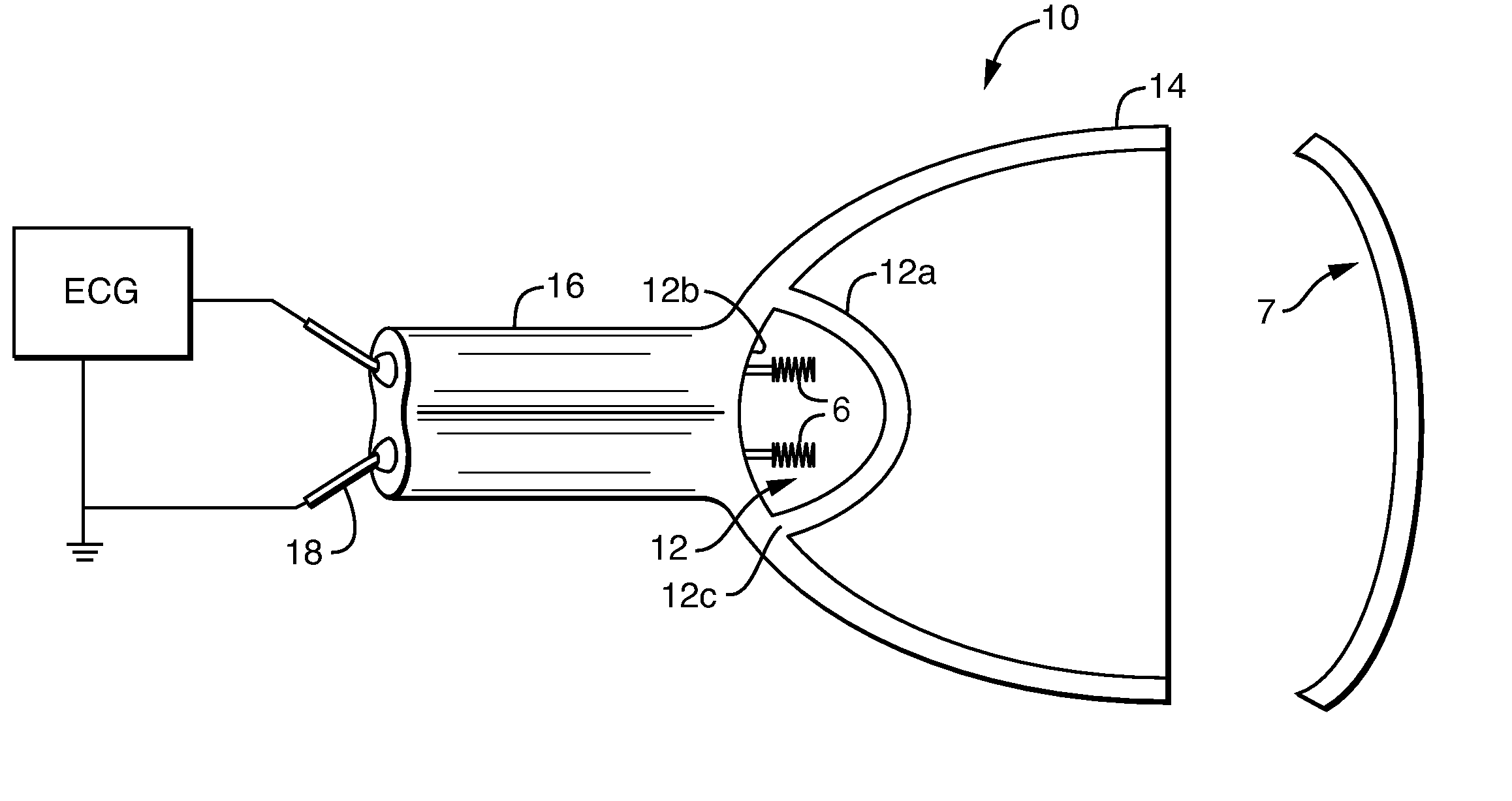
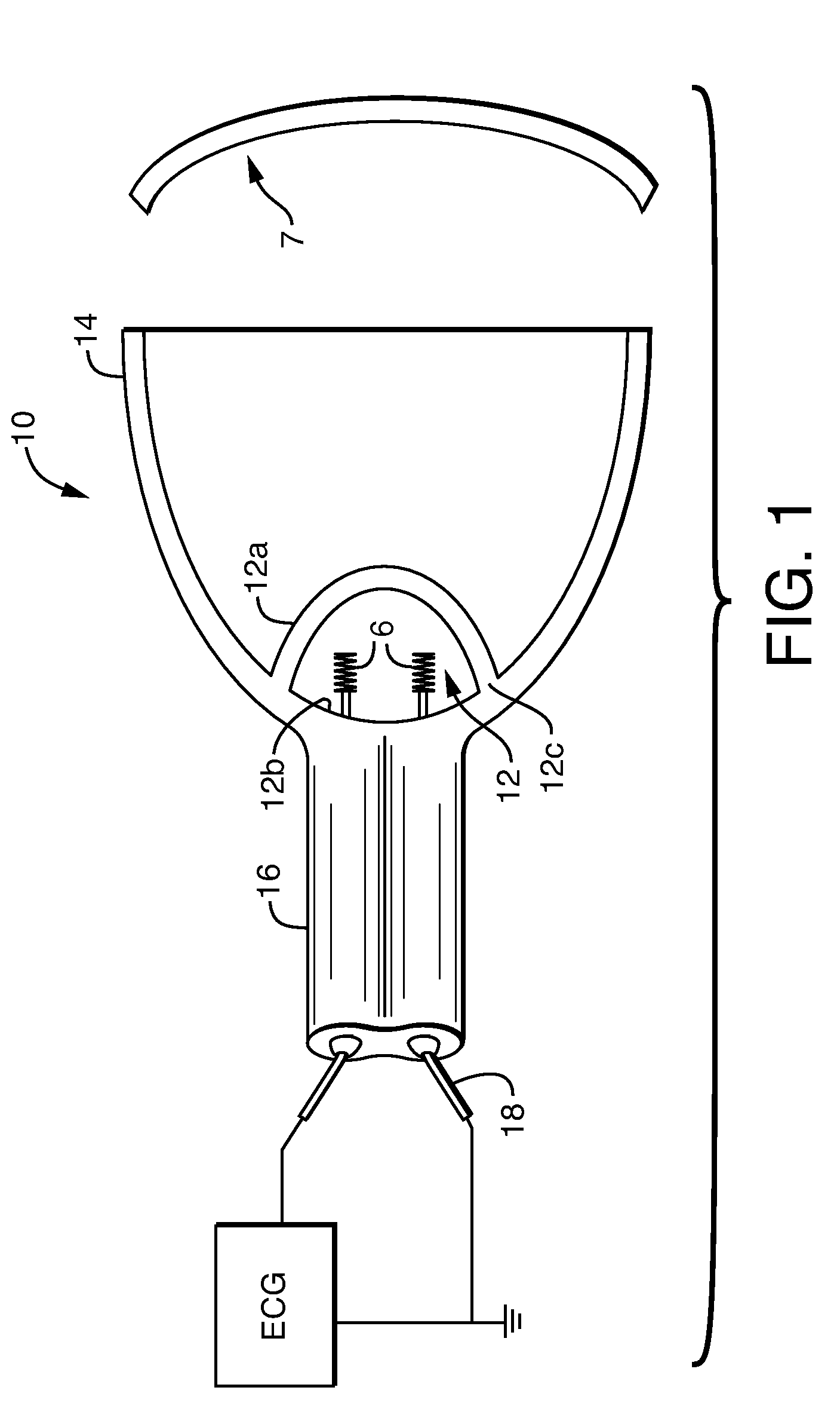
[0022]A more complete description is afforded by inspection of the drawings. FIG. 1 shows the lamp of the present invention. The geometry of an elliptical reflector suitable for the present invention is shown in FIG. 6. The lamp 10 includes a ceramic discharge chamber 12 that is positioned so the arc is at focus F′ of ceramic reflector 14. The reflector 14 collects the light from the discharge chamber 12 and focuses it to F. A ceramic capillary 16 is provided and includes two electrodes 18 that extend into the discharge chamber so that an imaginary line between the tips 6 of the electrodes intersects the focus F′. The discharge chamber 12 includes two concave parts 12a and 12b (right and left parts of the chamber 12 in FIG. 1) attached to each other at a seam 12c, where the ceramic reflector 14 is directly attached to an exterior surface of the discharge chamber 12 at the seam 12c, such as shown in FIG. 1. Preferably, the concave parts are generally hemispherical. Generally hemisphe...

second embodiment

[0027]If the desired discharge cavity volume and placement at the focal point of the reflector are not compatible with the shape shown in FIG. 1 (for example, operation at lower wattage requires a smaller discharge volume), the discharge cavity 12 can be produced as a small isolated cavity positioned further inside the reflector 14 as shown in FIG. 4. This allows maximum flexibility in controlling discharge cavity volume and focal position. This configuration could be produced by using three ceramic shapes as shown in FIGS. 5a, b and joined together to form the final component. As shown in FIG. 5a, the capillary component may first be joined to the portion completing the closure of the discharge cavity using thermal or chemical joining. The reflector could then be slid onto the capillary portion as shown in FIG. 5b. The bonding of the reflector to the capillary portion could be done in the green state by thermal or chemical joining, in the pre-fired state using an interference fitti...


PUM

PropertyMeasurementUnit
pressureaaaaaaaaaa
pressureaaaaaaaaaa
angleaaaaaaaaaa

Abstract

A ceramic discharge lamp and a method of making the lamp includes a ceramic discharge chamber with two concave parts that are attached to each other at a seam, and a ceramic reflector directly attached to an exterior surface of the discharge chamber at the seam, or directly attached to a ceramic capillary that is attached to one of the two concave parts. The lamp finds particular application where focused light is required, such as injection of light into a fiber optic device. The lamp can be very small and has an advantage that the discharge chamber is isolated from the reflective surfaces so that the optically active parts of the reflector are not covered with salt from the preferred metal halide lamp fill.

Description

BACKGROUND OF THE INVENTION[0001]Miniature metal halide lamps have been on the market for some time, where the lamps are designed to be small and provide concentrated sources of light for inclusion into reflectors. The objective is to gather and focus or collimate the light for projection applications or injection into fiber optics for decorative or medical applications. Examples of this are well known in the art: vitreous silica high-intensity discharge (HID) lamps for automotive headlamps that project a beam for driving at night, and short-arc rare gas lamps for fiber illuminators. Recently the vitreous silica headlamps have been augmented with ceramic metal halide lamps of small dimensions for similar purposes as taught by Guenther U.S. Pat. No. 7,045,960; Wijenberg et. al. WO2004 / 023517 A1; Hendricx et. al. WO2005 / 088673 A2; and Selezneva et. al. US 2007 / 0120492 A1. The lamps may or may not contain mercury. An example of a lamp used for medical applications, namely fiber optic i...

Claims


Application Information

Patent Timeline
Patent Type & Authority Applications(United States)
IPC IPC(8): H01J17/16
CPCF21V7/04H01J9/266H01J61/365H01J61/125H01J61/025
Inventor LAPATOVICH, WALTER P.NEIL, JEFFREY T.
Owner OSRAM SYLVANIA INC
Learn More