
Re-configurable armored tactical personnel and collective training facility

a technology for tactical personnel and training facilities, applied in ventilation systems, heating types, instruments, etc., can solve the problems of not being as realistic as conventional looking walls, not being able to achieve the effect of most lethal encounters, and not adequately training military and law enforcement personnel for many real life situations

Inactive Publication Date: 2009-11-19
UXB INT
View PDF35 Cites 46 Cited by
  • Summary
  • Abstract
  • Description
  • Claims
  • Application Information

AI Technical Summary

Problems solved by technology

However, target practice on a range does not adequately train military and law enforcement personnel for many real life situations.
While these shoot houses provided a marked improvement over traditional training at a target range, they still do not feel as realistic as conventional looking walls.
While the basics of weapons handling and marksmanship are important skills for all shooters, they are not the basis for success during most lethal encounters involving the defensive use of a firearm.
As such, static (non-automated) outdoor ranges with permanent target positions are least desirable to meet the changing mission requirements for these training exercises.
With regard to tactical training, the traditional shoot house is also not fully adequate or desirable because of life cycle costs and lack of an opposing force in live training scenarios.
Further, the traditional shoot house requires significant design time and construction efforts to erect.
Furthermore, the traditional shoot house lacks flexibility in modifying training scenarios once erected.
Additionally, the traditional shoot house lacks realism for today's training mission requirements.
Also, the traditional shoot house includes a large surface danger zone (SDZ) footprint.
In addition, the traditional shoot house typically raises encroachment, nuisance, and / or noise issues.
Furthermore, traditional shoot houses typically have an open top due to air quality issues among other things.

Method used


Image

  • Re-configurable armored tactical personnel and collective training facility
  • Re-configurable armored tactical personnel and collective training facility
  • Re-configurable armored tactical personnel and collective training facility

Examples


Embodiment Construction

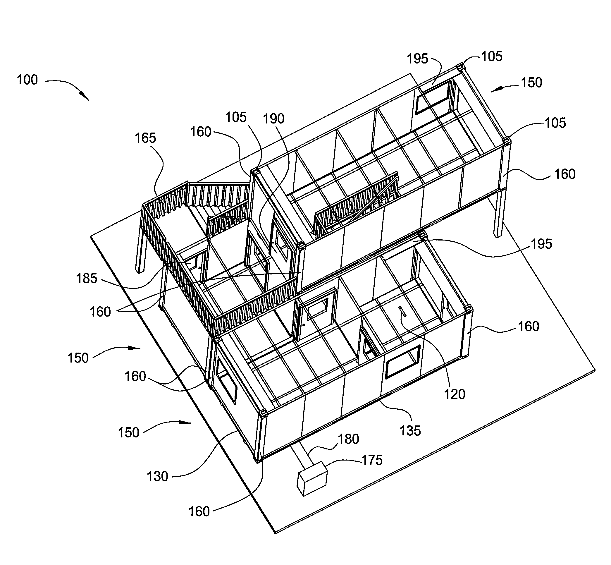
[0022]The present invention is generally directed to a modular unit for use in force-on-force training exercises in order to train fighters as they fight. Various terms as used herein are defined below. To the extent a term used in a claim is not defined below, it should be given the broadest definition persons in the pertinent art have given that term, as reflected in printed publications and issued patents. In the description that follows, like parts are marked throughout the specification and drawings with the same reference numerals. The drawings may be, but are not necessarily, to scale and the proportions of certain parts have been exaggerated to better illustrate details and features described below. One of normal skill in the art of shoot houses will appreciate that the various embodiments of the invention can and may be used in all types of shoot houses.

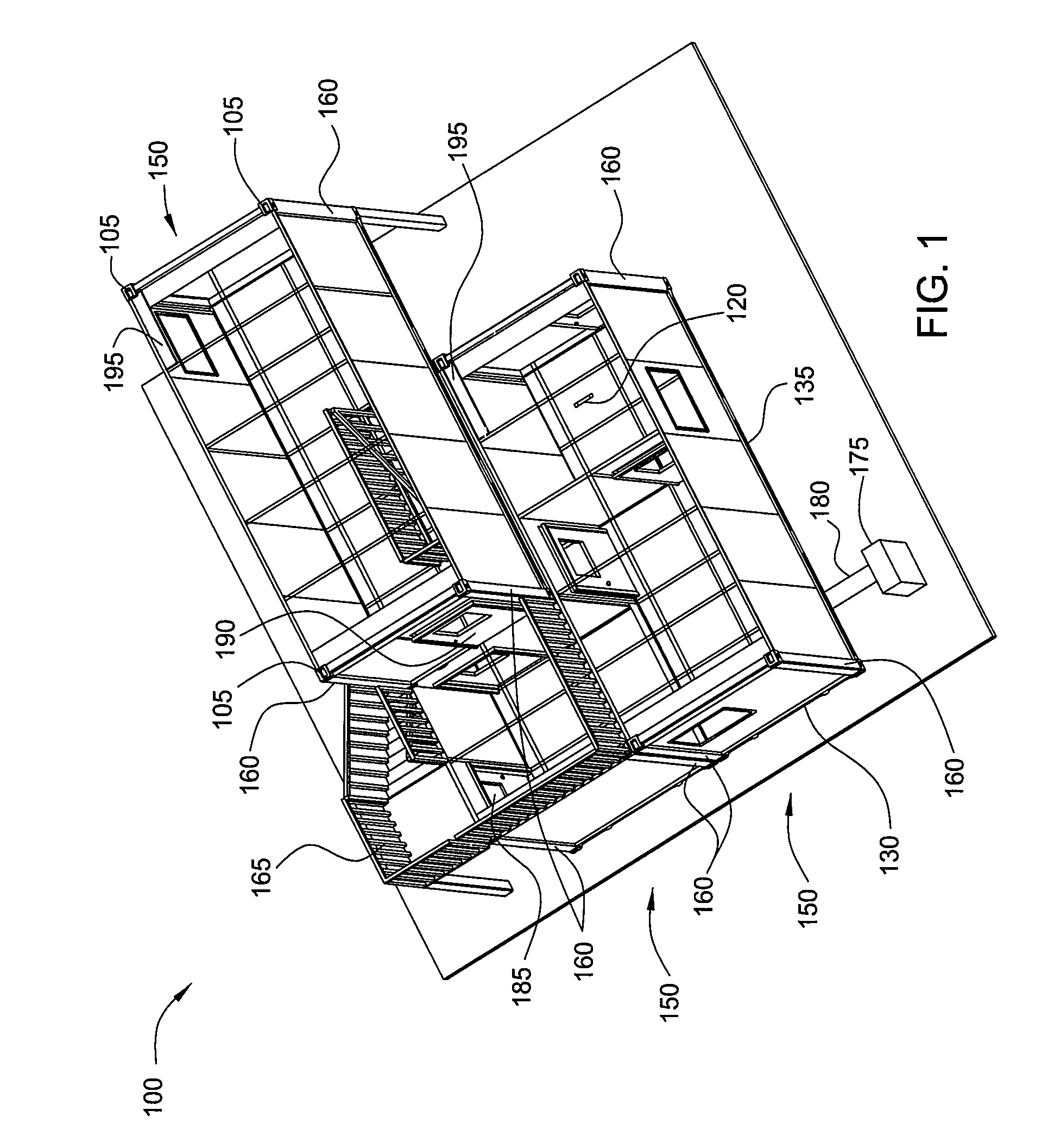
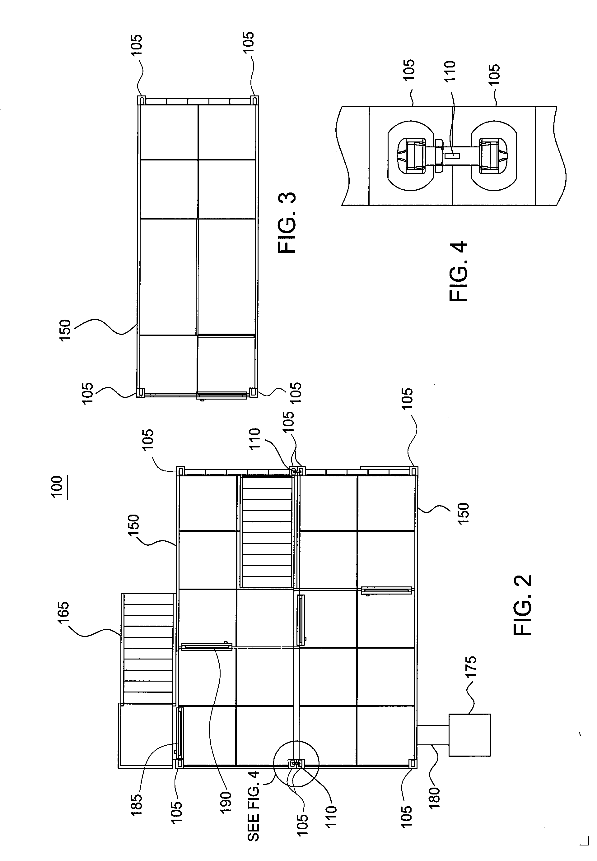
[0023]FIG. 1 is a view illustrating one embodiment of a reconfigurable armored tactical personnel and collective training ...


PUM


Abstract

The present invention is generally directed to a reconfigurable armored unit for use in training exercises. In one aspect, a reconfigurable training facility is provided. The reconfigurable training facility includes a first modular unit. The reconfigurable training facility further includes a second modular unit, wherein each modular unit includes a frame with corner connection members and a grid system, whereby the corner connection members are used to connect the modular units together and whereby the grid system is used to selectively support a plurality of panels. In another aspect, a modular unit for use in a reconfigurable training facility is provided. In yet another aspect, a method of forming a reconfigurable training facility is provided.

Description

CROSS-REFERENCE TO RELATED APPLICATIONS[0001]This application is a continuation-in-part of U.S. patent application Ser. No. 11 / 283,630, filed on Nov. 21, 2005, which is herein incorporated by reference.BACKGROUND OF THE INVENTION[0002]1. Field of the Invention[0003]Embodiments of the present invention generally relate to a training facility for military and law enforcement personnel. More particularly, embodiments of the present invention pertain to a reconfigurable armored unit for use in training exercises.[0004]2. Description of the Related Art[0005]To maintain proficiency in the use of firearms, typically military and law enforcement personnel engage in target practice. Traditionally, target practice has been conducted on a range in which targets were placed a distance away from the shooter. However, target practice on a range does not adequately train military and law enforcement personnel for many real life situations. Therefore, structures that include ballistic walls in arra...

Claims


Application Information

Patent Timeline
Patent Type & Authority Applications(United States)
IPC IPC(8): E04H1/00E04H9/00G09B9/00F41G3/26F41H5/24E04B1/00F41J1/00F24F7/00
CPCE04H9/10
Inventor WARMINSKY, MICHAEL F.
Owner UXB INT
Learn More