
Power Transmission Device, Power Transmission Method, Program, Power Receiving Device and Power Transfer System

a technology of power transmission device and power receiving device, which is applied in the direction of process and machine control, material dimension control, instruments, etc., can solve the problems of reducing the power transmission efficiency of the power receiving device, increasing the number of faults caused by the power receiving device described above, and causing heat generation and power receiving device failures

Active Publication Date: 2009-11-12
SONY CORP
View PDF2 Cites 466 Cited by
  • Summary
  • Abstract
  • Description
  • Claims
  • Application Information

AI Technical Summary

Benefits of technology

[0007]In a power transfer system that transfers power in a non-contact manner, user convenience is increased as a power transmission device becomes increasingly capable of transferring still larger power to a power receiving device at still greater distances.
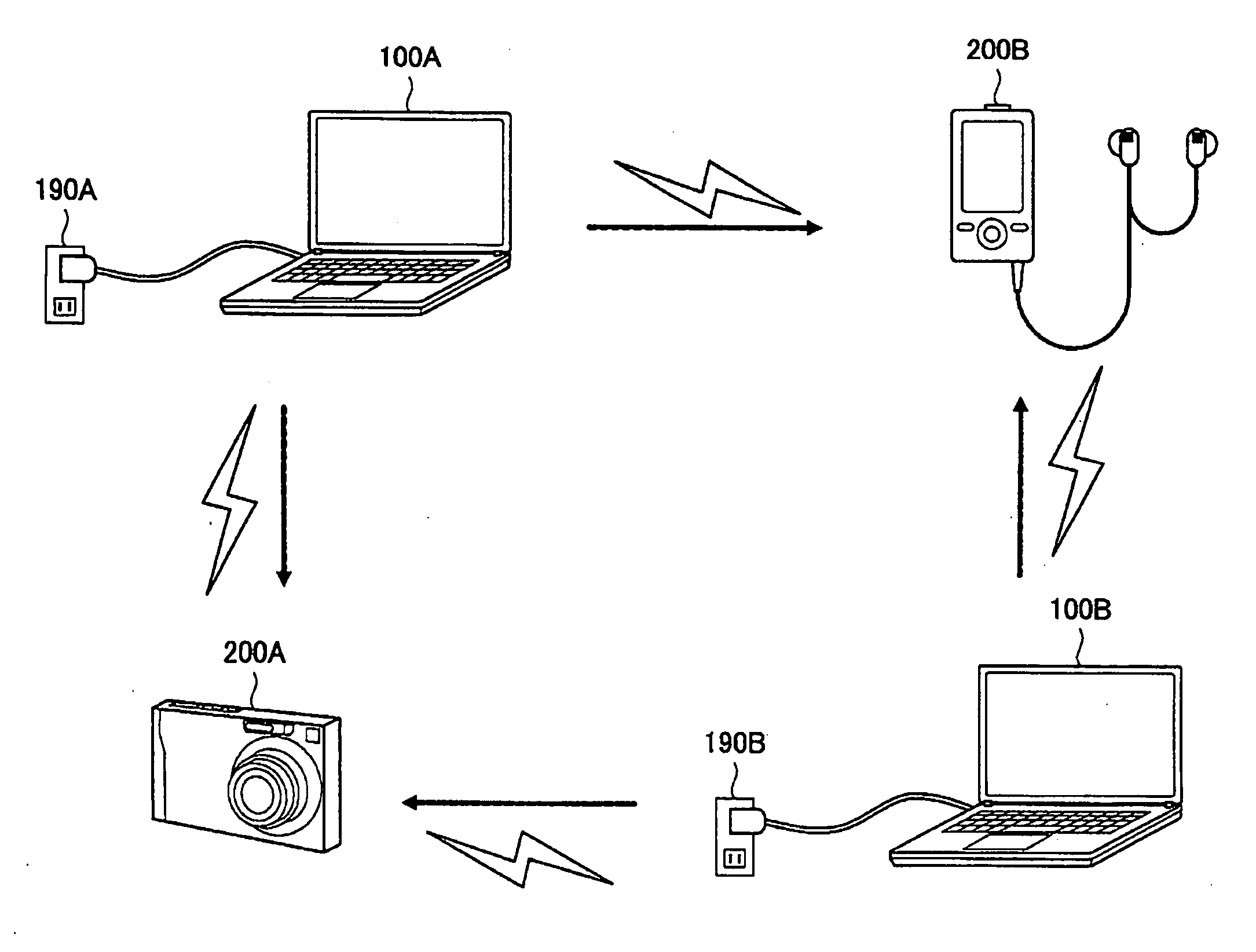
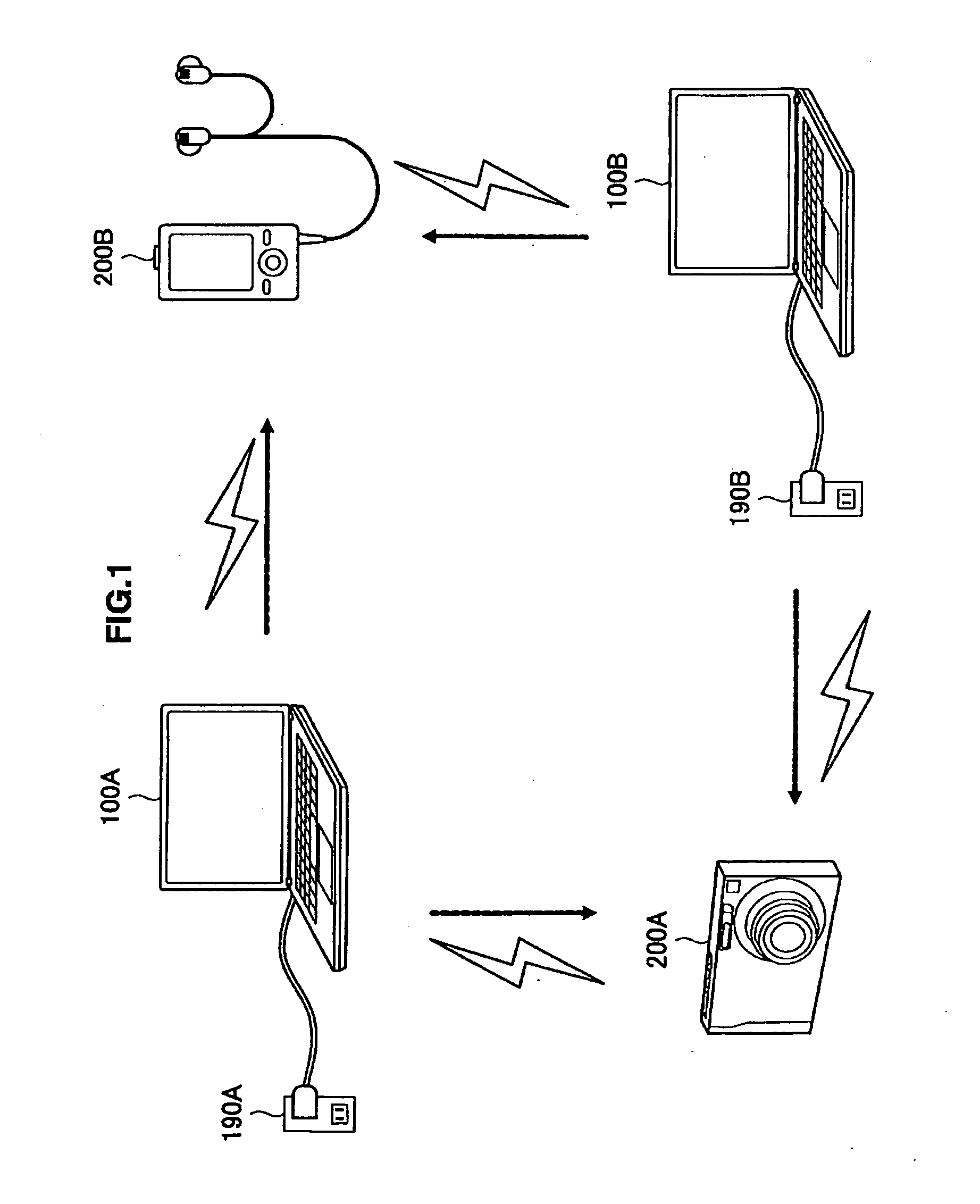
[0022]By using such a method, even if a plurality of power transmission devices is present, power can be transmitted from one power transmission device to one power receiving device without being interfered by other power transmission devices.
[0030]According to the embodiments of the present invention described above, even if a plurality of power transmission devices is present, power can be transferred from one power transmission device to one power receiving device without being interfered by other power transmission devices.

Problems solved by technology

Since the power receiving device may receive more power than necessary in the above case, for example, there is a possibility that various kinds of faults such as heat generation and power receiving device failures are caused due to surplus power.
Here, the possibility that various kinds of faults are caused in the power receiving device described above increases as it becomes possible to transfer still larger power for still greater distances.
In the above case, however, with the presence of a magnetic field (or an electric field) having the same frequency and a different phase, transfer efficiency of power is lowered due to obstruction of a resonance operation by the other magnetic field (or the other electric field) in the power receiving device.
Therefore, if a plurality of power transmission devices is present in a power transfer system in related art, it is difficult to transfer power from one power transmission device to one power receiving device without being interfered by another power transmission device.

Method used


Image

  • Power Transmission Device, Power Transmission Method, Program, Power Receiving Device and Power Transfer System
  • Power Transmission Device, Power Transmission Method, Program, Power Receiving Device and Power Transfer System
  • Power Transmission Device, Power Transmission Method, Program, Power Receiving Device and Power Transfer System

Examples


first example

(i) First Example

[0236]FIG. 23 is an explanatory view showing a first example of the received power level detection circuit 350 according to the second embodiment of the present invention. Referring to FIG. 23, a received power level detection circuit 350A according to the first example includes a resistor R1, a light emitting diode LED, a photodiode PD, and a resistor R2. Here, if a load current in accordance with the first transmission power Ptrans(p) is passed to the light emitting diode LED, the light emitting diode LED emits light in accordance with the load current. The photodiode PD plays the role of a so-called photo-detector and detects lights emitted from the light emitting diode LED. The photodiode PD outputs a current in accordance with a detected amount. The received power level detection circuit 350A can output a detection result in accordance with the received power level of the received first transmission power Ptrans(p) by outputting the current in accordance with t...

second example

(ii) Second Example

[0238]FIG. 24 is an explanatory view showing a second example of the received power level detection circuit 350 according to the second embodiment of the present invention. Referring to FIG. 24, a received power level detection circuit 350B according to the second example includes a resistor R3, a resistor R4, and a comparator Cmp. Here the resistor R3 and the resistor R4 produce a partial voltage in accordance with the first transmission power Ptrans(p) and the comparator Cmp compares the partial voltage with a reference voltage Vo. Then, the comparator Cmp outputs the voltage in accordance with a comparison result as a detection result. Therefore, the received power level detection circuit 350B can output a detection result showing whether or not the received power level of the received first transmission power Ptrans(p) satisfies a predetermined level.

[0239]Here, the resistor R3 and the resistor R4 shown in FIG. 24 correspond to a measuring load circuit to deri...

third example

(iii) Third Example

[0240]FIG. 25 is an explanatory view showing a third example of the received power level detection circuit 350 according to the second embodiment of the present invention. Referring to FIG. 25, a received power level detection circuit 350C according to the third example includes a resistor R5, an inductor L5, and a switch SW3 to constitute an electromagnetic relay switch. Here, with a load current in accordance with the first transmission power Ptrans(p) being passed to the inductor L5, a magnetic field in accordance with the load current is generated. Then, with a switching operation in accordance with strength of the magnetic field in accordance with the load current being performed by the switch SW3, a detection result output from the received power level detection circuit 350C changes. Therefore, the received power level detection circuit 350C can output a detection result in accordance with the received first transmission power Ptrans(p).

[0241]The received po...


PUM


Abstract

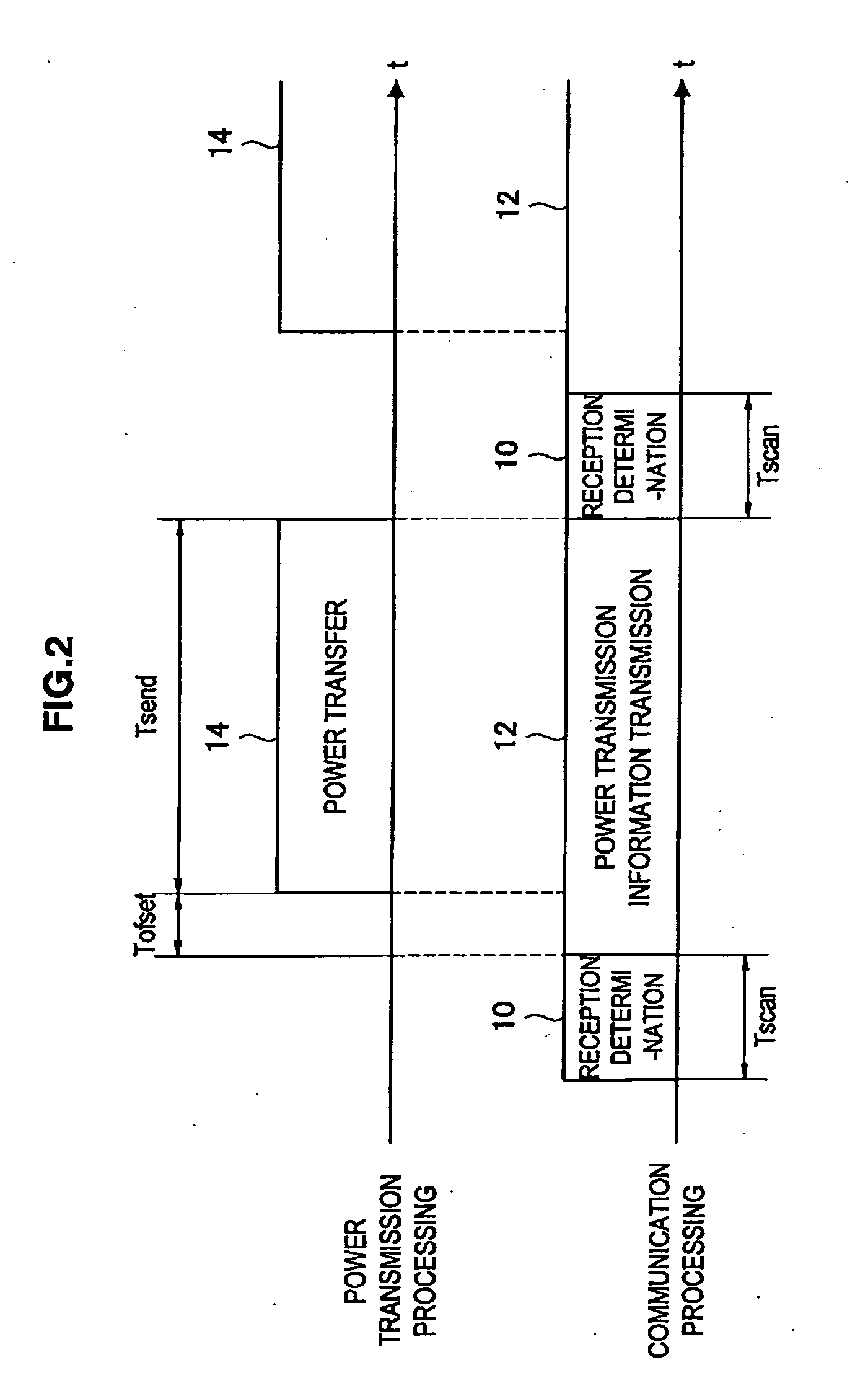
There is provided a power transmission device including a communication part that performs communication with an external power transmission device that transmits power, a power transmission part that transmits power to a power receiving device that receives the transmitted power in a non-contact manner, a determination part that determines whether power can be transmitted, based on external power transmission information received by the communication part indicating a start of power transmission by the external power transmission device, and a power transmission control part that controls the power transmission part to selectively transmit power based on a determination result from the determination part.

Description

BACKGROUND OF THE INVENTION[0001]1. Field of the Invention[0002]The present invention relates to a power transmission device, power transmission method, program, power receiving device, and power transfer system.[0003]2. Description of the Related Art[0004]In recent years, a power transfer system capable of transferring power between devices in a non-contact manner has become widely available. The power transfer system includes, for example, an IC card system in which a reader / writer (an example of the power transmission device) and an IC card (an example of the power receiving device) are used such as an electronic money system, a ticket gate system of transportation facilities, and a building / room admission system using an employee ID card or the like.[0005]In the meantime, a technology to transfer still larger power for still greater distances has been developed. See, for example, Non-patent Document 1 for a technology to transfer power by using resonance of an electric field or ...

Claims


Application Information

Patent Timeline
Patent Type & Authority Applications(United States)
IPC IPC(8): G06F1/28H02J50/00H02J50/10H02J50/12H02J50/20H02J50/40H02J50/80
CPCH02J17/00H02J5/005H02J50/12H02J50/80H02J50/40H02J50/20
Inventor WAKAMATSU, MASATAKA
Owner SONY CORP
Learn More