
Image sensor with integrated region of interest calculation for iris capture, autofocus, and gain control

a technology of image sensor and region of interest, applied in the field of image sensor with integrated region of interest calculation for iris capture, autofocus, and gain control, can solve the problems requiring iom system expensive, and system not relying on nir imagery, etc., to achieve the effect of reducing the gain associated with image sensor

Active Publication Date: 2009-11-12
PRINCETON IDENTITY INC
View PDF16 Cites 54 Cited by
  • Summary
  • Abstract
  • Description
  • Claims
  • Application Information

AI Technical Summary

Benefits of technology

"The present invention provides an iris recognition system and method that can locate and identify an iris from an image taken by a camera. The system includes an image sensor, a buffer, comparator, autofocus logic, and gain control logic. The image sensor captures an image of a subject and the buffer stores values associated with the pixels in the image sensor. The comparator identifies the iris based on the brightness values of the pixels in a brightest pixel set. The system can adjust the focus of the lens and gain control of the image sensor based on the brightest pixels in the image. The system can also include a plurality of illuminators for illuminating the subject and a translator for translating linear addresses into row and column addresses for the image sensor. The system can also repeat steps to obtain a second plurality of values associated with the brightest pixels and adjust the gain control of the image sensor based on the highest value of the second plurality of values. The technical effects of the invention include improved accuracy and efficiency in identifying the iris and improved autofocus capabilities."

Problems solved by technology

The specialized hardware was external to the camera sensor itself, which rendered the IOM system expensive.
There exists systems that are less expensive than IOM that rely on visible light cell phone camera technology, however, such systems do not rely on NIR imagery and are considerably less accurate than NIR-based systems.

Method used


Image

  • Image sensor with integrated region of interest calculation for iris capture, autofocus, and gain control
  • Image sensor with integrated region of interest calculation for iris capture, autofocus, and gain control
  • Image sensor with integrated region of interest calculation for iris capture, autofocus, and gain control

Examples


Embodiment Construction

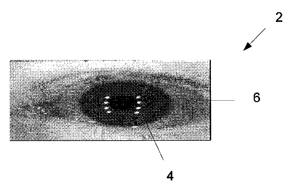
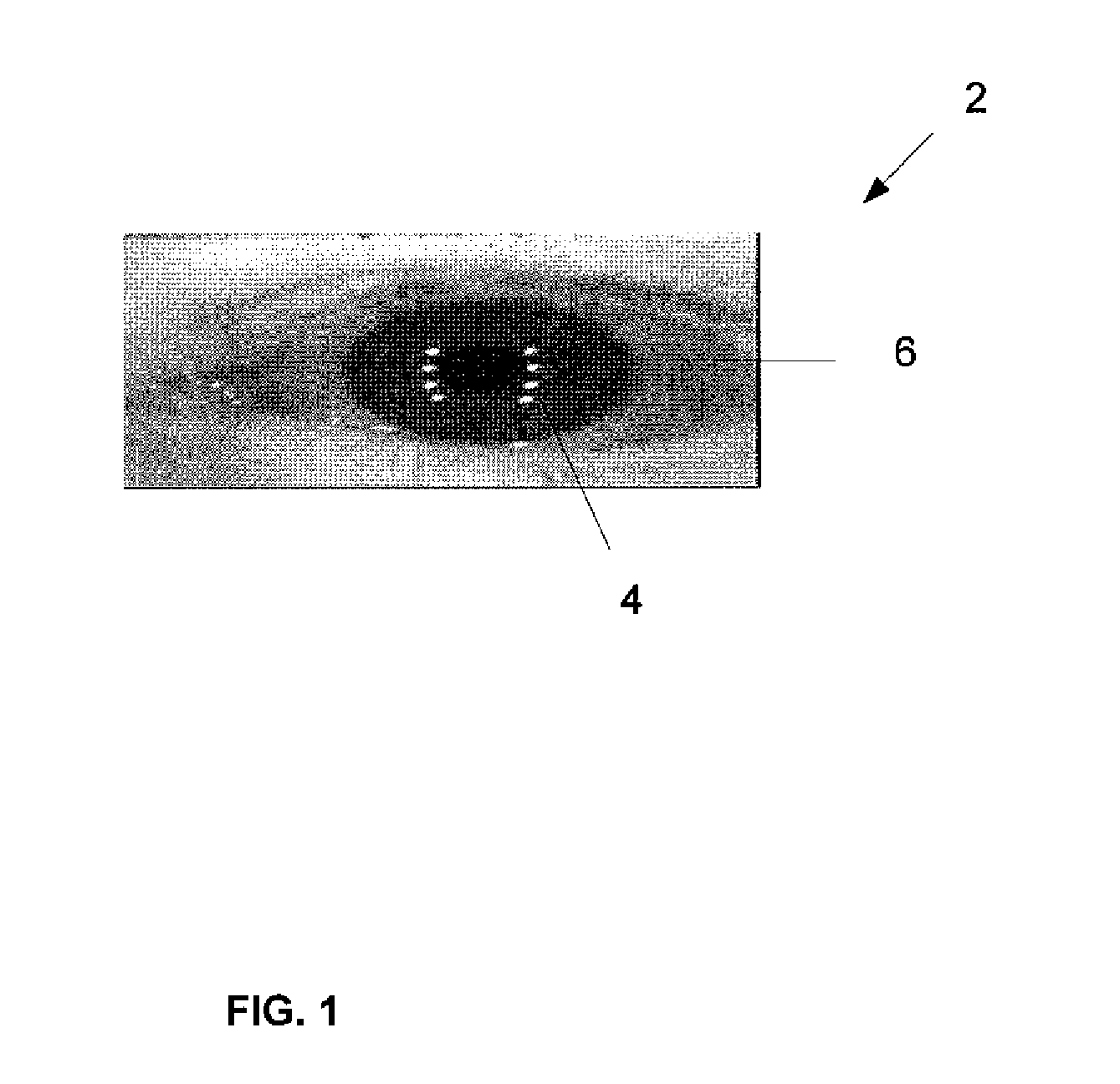
[0022]FIG. 1 illustrates an image 2 of an eye 6 in which a pattern of bright reflected spots (specularities) 4 results from illumination with an illumination source. In an embodiment of the present invention, a plurality of NIR illuminators provides short duration (i.e., strobed) high intensity light upon a subject (i.e., a human). According to an embodiment of the present invention, an iris of the eye is identified and located by obtaining a brightest pixel set in an image of the eye. The brightest pixel set correspond to the specularities provided by the illuminators. A system for capturing an iris image may comprise any number of illuminators. According to an embodiment of the present invention, eight illuminators may be employed, as illustrated by the 8 specularity spots shown in FIG. 1.

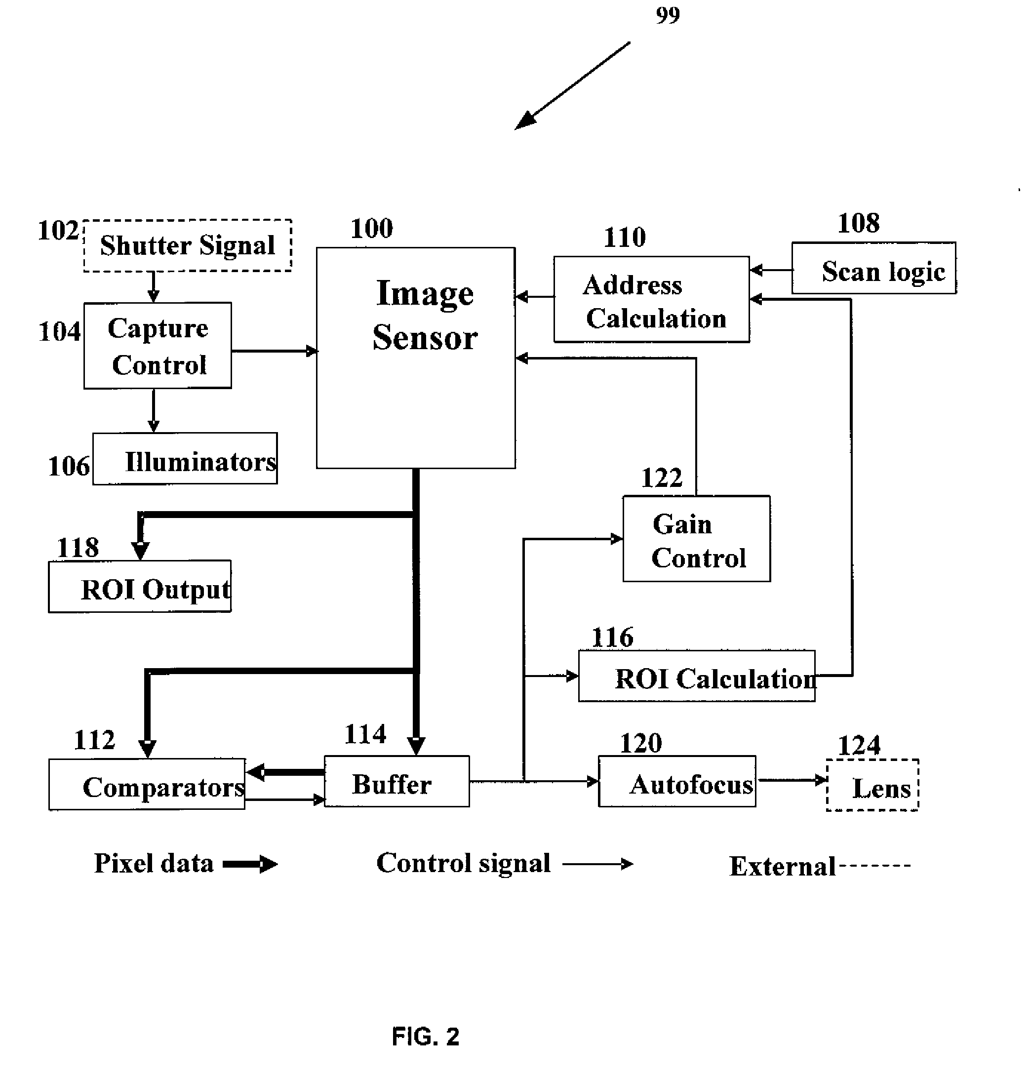
[0023]FIG. 2 depicts a block diagram of an exemplary system configured to implement a coarse segmentation of an iris from an image, according to an embodiment of the present invention. The iris r...


PUM


Abstract

An iris recognition system and method for operating same is disclosed. The iris recognition system includes an image sensor, a buffer, a comparator, autofocus logic, and gain control logic. The image sensor is configured to obtain at least one image from a camera. The buffer communicatively connected to the image sensor stores values associated with the pixels in the image sensor. The comparator communicately connected to the buffer obtains a coarse segmentation of an iris of a subject. The autofocus logic for adjusts the focus of a lens associated with the camera. The gain control logic adjusts the gain of the image sensor. The functions of obtaining a coarse segmentation, adjusting the focus of the lens, and adjusting the gain are based on the locations of the pixels with the highest value in the image sensor as stored in the buffer.

Description

CROSS-REFERENCE TO RELATED APPLICATIONS[0001]This application claims the benefit of U.S. provisional patent application No. 61 / 052,494 filed May 12, 2008, the disclosure of which is incorporated herein by reference in its entirety.FIELD OF THE INVENTION[0002]The present invention relates generally to iris recognition systems, and more particularly, to a method for providing coarse segmentation of an iris (capture), autofocus, and automatic gain control in iris recognition circuits.BACKGROUND OF THE INVENTION[0003]Iris recognition is widely regarded as one of the most reliable biometric identifiers currently available. The accuracy of iris recognition systems is currently on par with fingerprints and, given the correct state of the art, better than facial recognition techniques. An iris pattern is unique to any individual eye: the irises of each eye are different for an individual and even between identical twins.[0004]The majority of commercial iris recognition systems are based on ...

Claims


Application Information

Patent Timeline
Patent Type & Authority Applications(United States)
IPC IPC(8): H04N7/18G06K9/00H04N5/235H04N5/335H04N25/00
CPCG06K9/0061G06K9/3241H04N5/2354H04N5/23212H04N5/2351H04N5/2256G06V40/193G06V10/255H04N23/56H04N23/673H04N23/71H04N23/74
Inventor TINKER, MICHAELACKERMAN, DAVID ALANKOLCZYNSKI, RAYMONDBERGEN, JAMES
Owner PRINCETON IDENTITY INC
Learn More