Guiding and shaping system

a technology of shaping system and guiding rod, which is applied in the direction of resistive welding apparatus, arc welding apparatus, manufacturing tools, etc., can solve the problems of pipe shaped and welded using the known methods, inhomogeneity cannot be avoided, and easy burst of pipes, etc., and achieves the effect of convenient us

Inactive Publication Date: 2009-11-12
WUPPERMANN EDELSTAHLTECHN
View PDF40 Cites 4 Cited by
  • Summary
  • Abstract
  • Description
  • Claims
  • Application Information

AI Technical Summary

Benefits of technology

[0013]An object of the present invention is therefore an apparatus for welding pipes made from metallic strip material, in the case of which bursting of the pipes is avoided. The weld is to be executed in such a way that virtually no inhomogeneities occur. The design of the novel apparatus is to be so simple that it is easy to use.
[0026]The most important advantage of laser welding is the outstanding seam quality. The weld rate is generally also higher than in the case of TIG welding. However, the effect of heating the pipe material is substantially less than in the case of TIG welding.
[0036]When shaping the pipe from the metal strip with the aid of the compression rolls, different thicknesses of the material easily occur, depending on the metal used.
[0044]Consequently, the strip edges can be held against one another precisely and calibrated even if different material thicknesses or material geometries are welded to one another. The bearing pressures can respectively be regulated separately and controlled electronically per compression roll such that irregularities in the strip widths accompanied by a resulting basic cross section of the pipes to be shaped that is deviant are likewise automatically eliminated. Furthermore, the possibility is thereby provided of optimizing the forces on each workpiece edge or wall thickness to the extent that there is an optimum melting process irrespective of which welding technique is used.

Problems solved by technology

However, this frequently leads to offsetting the two edges from one another, and this leads to inhomogeneities that must later be compensated.
However, the inhomogeneities are not avoided with this method.
The pipes shaped and welded using the known methods burst easily, because stresses occur in the crystal structure of the welded tube.

Method used


Image

  • Guiding and shaping system
  • Guiding and shaping system
  • Guiding and shaping system

Examples


Embodiment Construction

[0049]The present invention can be explained with reference to FIGS. 1 to 3.

[0050]FIG. 1 shows the inventive guiding or shaping system from the side.

[0051]FIG. 1 shows the inventive guiding or shaping system from the input (1) of the slotted pipe (12) from which the opening is closed by the welding apparatus (3). The pipe, not yet cooled, is supported by the floatingly mounted lateral rolls (4) until it cools. After being cooled, the pipe is conveyed in the feed direction through and out of the output (2).

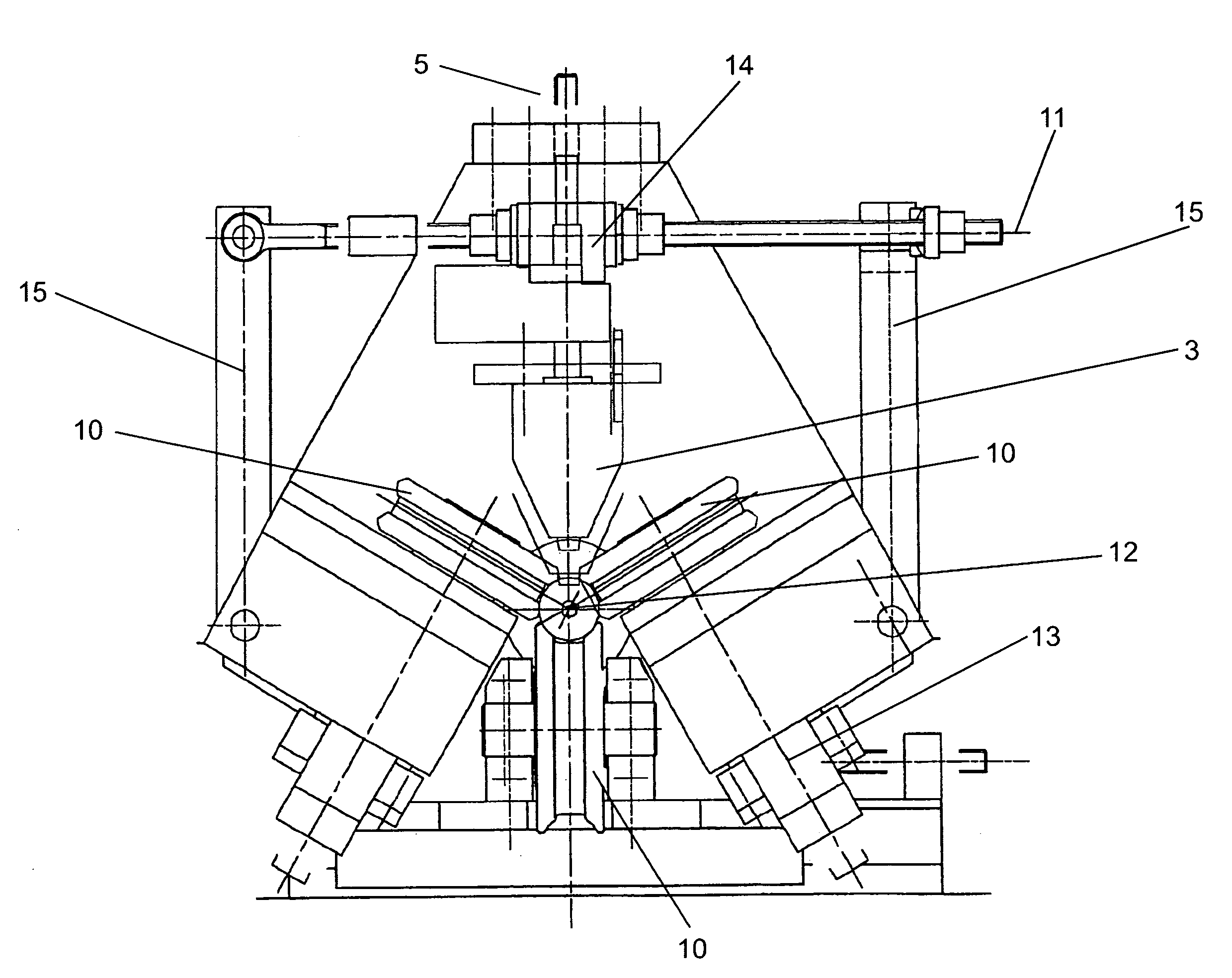
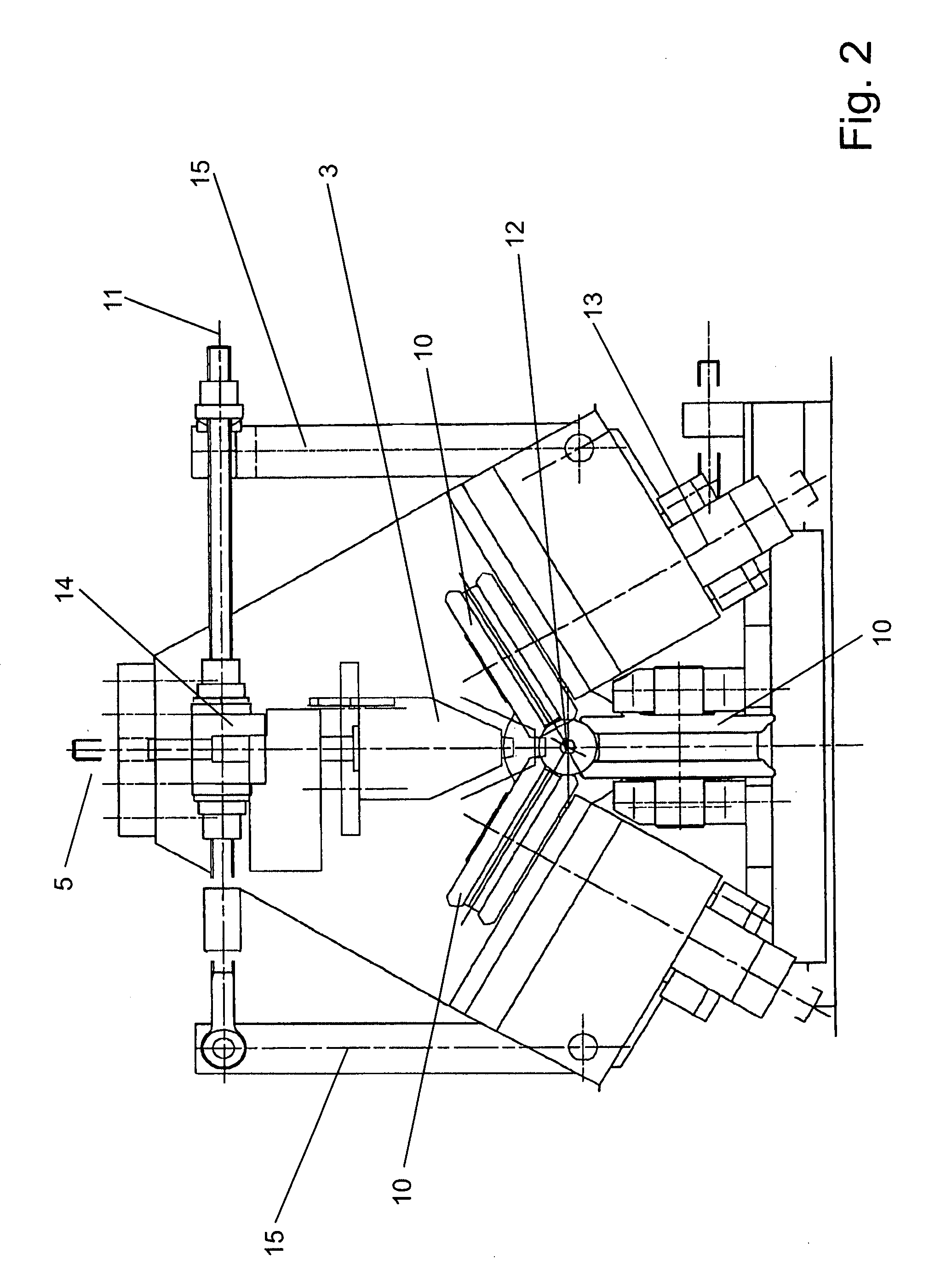
[0052]Upstream of the welding apparatus (3), the slotted pipe is compressed by the lower compression roll (9) and the right-hand and left-hand compression rolls (10). The central height adjustment adjusts the compression rolls (9 and 10) and the welding apparatus (3) as a function of the diameter of the pipe.

[0053]The optical strip edge detection system (7) controls the height adjustment (8) of the welding apparatus (3) as a function of the respective position of the strip edges.

[0...


PUM

PropertyMeasurementUnit
metallicaaaaaaaaaa
shapeaaaaaaaaaa
mechanical forcesaaaaaaaaaa

Abstract

A guiding and shaping system for producing welded pipes made from metallic strip material. The guiding and shaping system comprises several pairs of rolls that are disposed one behind another in the direction of travel of the workpiece and are used for increasingly cold-working and bending the edges of the workpiece as the workpiece advances. First pairs of rolls grip the top side and bottom side of the workpiece while pairs of rolls that grip the external faces of the bent edges and form the shape of a pipe are provided in the region where the bent edges form undercuts. The guiding and shaping system further comprises a welding device. The workpiece is supported by floatingly mounted lateral rolls until cooling off following the welding process.

Description

CROSS-REFERENCE TO RELATED APPLICATIONS[0001]This application is a National Stage application of International Application No. PCT / DE2006 / 000824, filed on May 11, 2006, which claims priority of German application number DE 10 2005 022 244.7, filed on May 13, 2005.BACKGROUND OF THE INVENTION[0002]1. Field of the Invention[0003]The invention relates to a guiding and shaping system for producing welded pipes made from metallic strip material, in the case of which pipes the strip edge (seam) is closed, for example, with the aid of a laser or by radiofrequency technology, to a method for producing welded pipes, and to the use of the guiding and shaping system to produce welded pipes.[0004]2. Description of the Prior Art[0005]The production of welded pipes made from metallic strip material is known (DE 35 29 160 A1). As a rule, in this case the initially strip-shaped workpiece (metallic strip material) is subjected in a cold state to ever stronger shaping of the edges. The first pair of r...

Claims


Application Information

Patent Timeline
Patent Type & Authority Applications(United States)
IPC IPC(8): B21C37/08
CPCB21D5/12B21C37/08
Inventor HARTMANN, MANFRED
Owner WUPPERMANN EDELSTAHLTECHN
Why Eureka
Try Eureka