Mask defogging system

a mask and head technology, applied in the direction of headwear caps, goggles, hats, etc., can solve the problems of exposing the face and head to possible serious injury, and a potential safety threat, and achieve the effect of hiccuping the ability of hearing

Inactive Publication Date: 2009-11-12
SALLEE MATTHEW BLAIR
View PDF6 Cites 25 Cited by
  • Summary
  • Abstract
  • Description
  • Claims
  • Application Information

AI Technical Summary

Benefits of technology

[0004]In regard to mask, helmet or goggle lenses, particularly masks, helmets or goggles used in the sport of paintball, in deference to the common problem of accumulated precipitation on the interior of a mask lens, commonly known as fog, which both prohibits a clear view of a person's surroundings and poses a potential safety threat as a mask must be removed fully or partially in order to wipe the interior of the lens free from precipitation, thereby exposing the face and head to possible serious injury. Moreover, to add an element of safety by creating a quieter system of fog removal than other products similar to this invention because any noise from the operation of the pump is away from the ears, or when built into or fastened onto a mask or helmet is buffered by the mask or helmet and further buffered by the addition of soundproofing material, thereby not hindering a person's ability to hear what is happening around them.

Problems solved by technology

In regard to mask, helmet or goggle lenses, particularly masks, helmets or goggles used in the sport of paintball, in deference to the common problem of accumulated precipitation on the interior of a mask lens, commonly known as fog, which both prohibits a clear view of a person's surroundings and poses a potential safety threat as a mask must be removed fully or partially in order to wipe the interior of the lens free from precipitation, thereby exposing the face and head to possible serious injury.

Method used


Image

  • Mask defogging system
  • Mask defogging system
  • Mask defogging system

Examples


Embodiment Construction

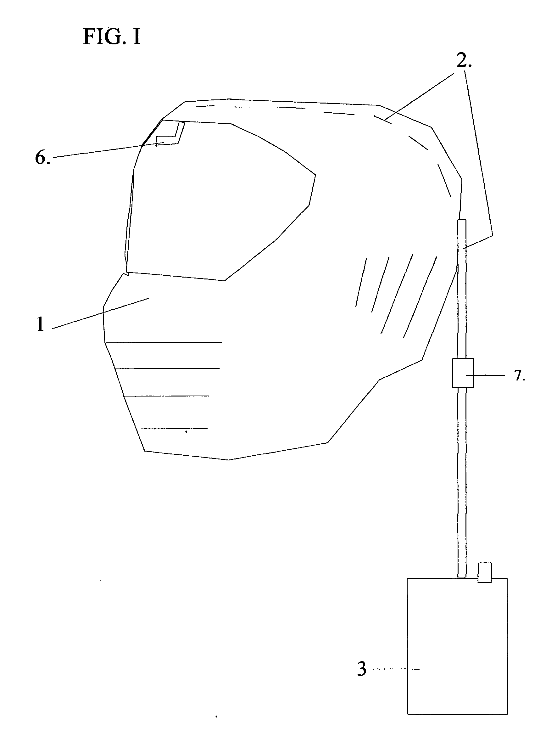
[0028]Referring to Figure I, the mask defogging system to be used with masks, helmets or goggles, particularly a paintball mask, employs a single or multiple flexible tube (2) of plastic or other flexible material for the purpose of carrying air into the interior of the mask (1) from any type of battery powered air pump or aerator (3) which is removably secured to a person by a clip or fastener whereby the end of tube which communicates with the interior of the mask ends in an air inlet piece, or airflow director (6) for the purpose of directing air directly onto the face of the lens, and dissipating or eradicating accumulated precipitation on the lens.

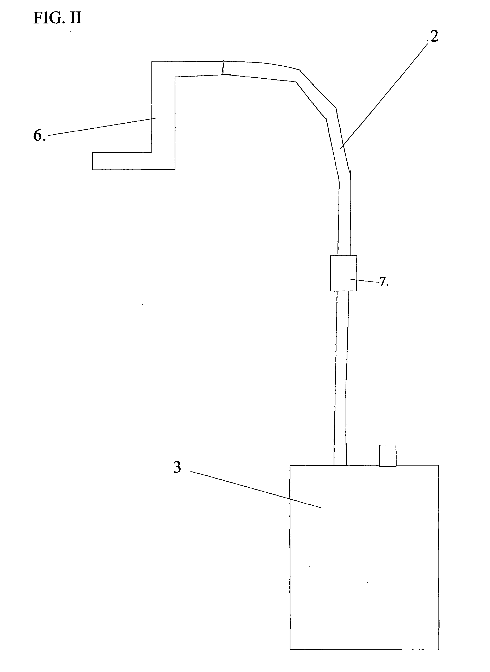
[0029]Referring to Figure II, a close-up of the mask defogging system to be used with masks, helmets or goggles, particularly a paintball mask, employs a battery operated air pump or aerator (3) which carries air through a single or multiple flexible tube or tubes (2) made of plastic, vinyl or other type of flexible material to create...


PUM


Abstract

A system for supplying and carrying air into the interior lens of a closed mask, helmet or goggle for the purpose of removing accumulated precipitation from the mask lens consisting of a battery powered air pump or aerator of any size or type which removably attaches to a person or a mask, helmet or goggle by a clip or other type of fastener which may be carried within a vest, belt pouch or on a belt pouch or on a belt or other form of carrying device or casing, or which may be build in as an integral part of a mask, helmet or goggle whereby air is carried from said pump through a single or multiple lines(s) of flexible plastic, vinyl or other type of flexible tubing or molded tubing which can be detached, or broken into two pieces, by a disconnect piece/connector (a quick disconnect piece) and whereby said tubing communicates between the pump outlet and the interior of the mask, helmet or goggle and air is directed onto the lens of the mask, helmet or goggle through some type of air inlet adapter, or air director piece, which is attached to the tubing for the purpose of directing the flow of air directly onto the interior lens of a mask, helmet or goggle for the purpose of dissipating or fully eradicating precipitation, or fog, as it is commonly called, from said lens and creating a clear view through said lens.

Description

BACKGROUND OF THE INVENTION[0001]The history of mask defogging systems is limited almost exclusively to a certain type of fan unit which is placed within a paintball mask (goggle) for the purpose of removing the accumulated precipitation, or “fog”, therein. Such a system, however, presents a safety risk because it limits a person's natural ability to fully hear what is going on around them because the unit is operating and creating noise in very close proximity to the ears, which leads to the inconvenience of having to turn the fan unit on and off throughout play or adapt to the noise.[0002]In addition, said fan units merely circulate the warm, humid air near the top of the head and face and fans it down into the mask, whereby this new defogging system pulls outside air in and forces a more concentrated air stream directly onto the lens of a mask, helmet or goggle, not merely fanning the air around. Similar concepts have been invented, but their scope and purpose were for radically ...

Claims


Application Information

Patent Timeline
Patent Type & Authority Applications(United States)
IPC IPC(8): A61F9/02A42B1/06
CPCA42B3/24
Inventor SALLEE, MATTHEW BLAIR
Owner SALLEE MATTHEW BLAIR
Why Eureka
Try Eureka