
Connection destination base station determination device

a technology of base station and determination device, which is applied in the field of cell phone mobile communications, can solve the problems of requiring a large amount of communications resources, requiring a large amount of communication resources, and requiring a long time for an appropriate connection destination

Inactive Publication Date: 2009-11-05
FUJITSU LTD
View PDF15 Cites 26 Cited by
  • Summary
  • Abstract
  • Description
  • Claims
  • Application Information

AI Technical Summary

Benefits of technology

[0013]Accordingly, it is a general object of the present invention to provide a connection destination base station determination device in which at least one of the above-described disadvantages are eliminated.
[0014]A more specific object of the present invention is to provide a connection destination base station determination device capable of improving the rate of new connections and improving the rate of handover success of a mobile terminal in a cellular communications system.
[0015]Another more specific object of the present invention is to provide a connection destination base station determination device capable of improving the rate of new connections and improving the handover success rate of a mobile terminal requesting high-speed data transmission.

Problems solved by technology

In particular, a mobile terminal that desires to transmit a large amount of data at high speed requires a large amount of communications resources.
In this case, the radio base station that provides the highest RSSI does not necessarily possess a sufficient amount of available resources for high-speed data transmission, and without it, a connection request is rejected.
Accordingly, according to this method, it is not less likely that a new connection request by a mobile terminal that desires high-speed data transmission will be rejected, thus causing a problem in that it takes a long time before an appropriate connection destination is found.
Accordingly, if the rate of use becomes relatively high-level, there may be a problem in that although the total amount of available resources of the radio base stations exceeds the amount of resources requested by a mobile terminal, none of the radio base stations satisfies the amount of resources requested by the mobile terminal, so that no connection can be made to any of the radio base stations.

Method used


Image

  • Connection destination base station determination device
  • Connection destination base station determination device
  • Connection destination base station determination device

Examples


Embodiment Construction

[0033]A description is given below, with reference to the accompanying drawings, of an embodiment of the present invention.

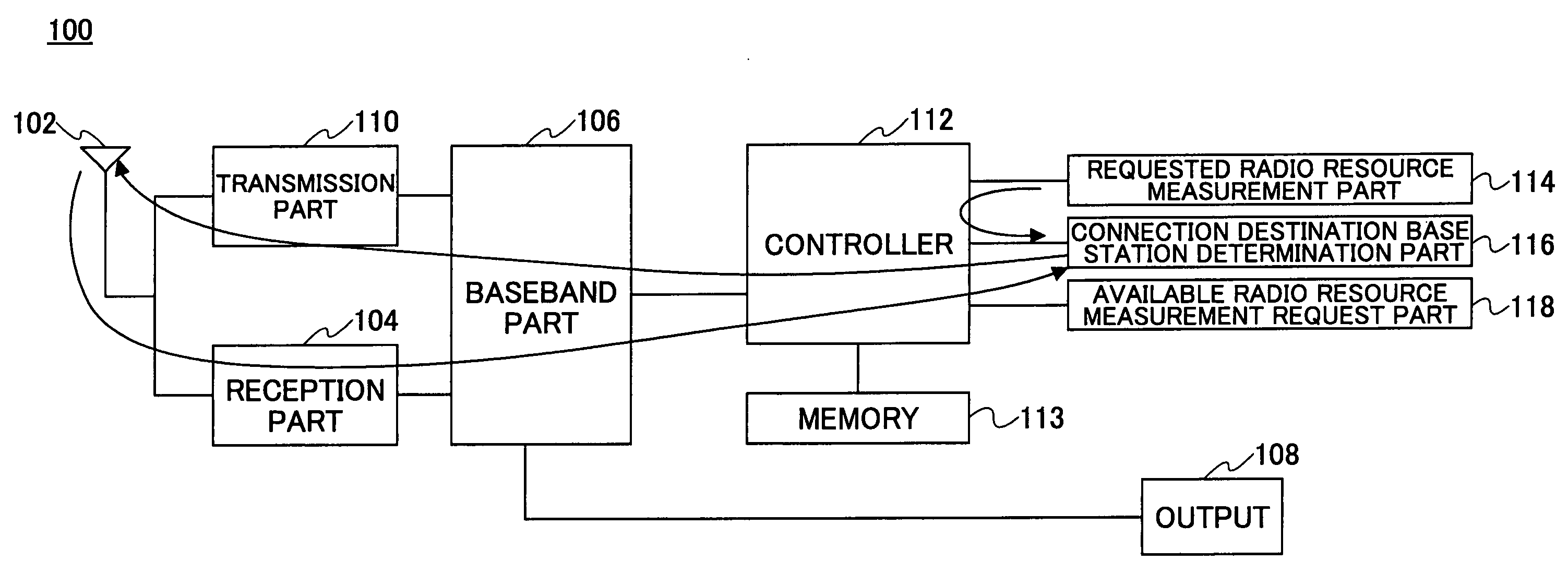
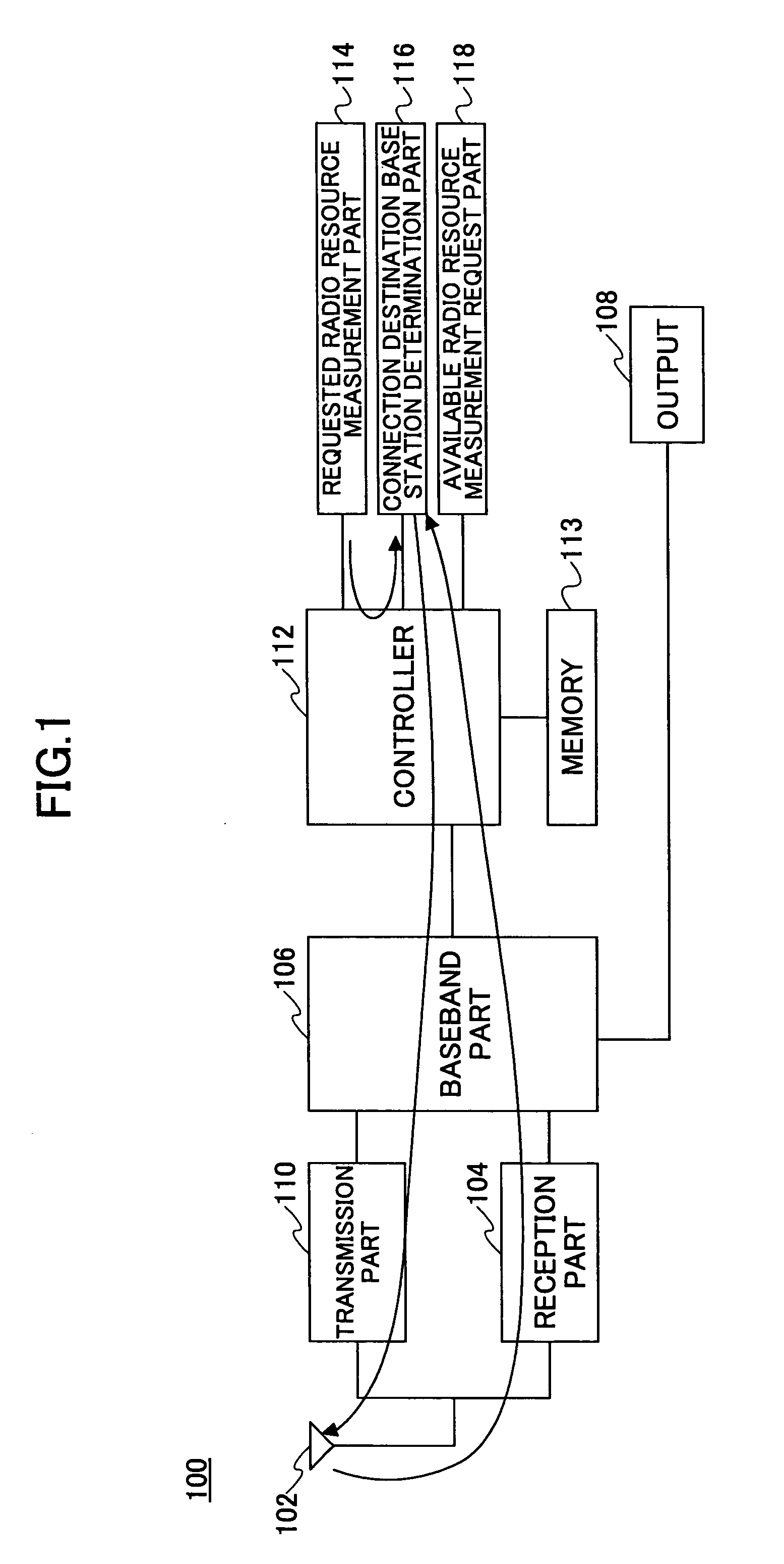
[0034]FIG. 1 shows the functional blocks of elements particularly related to the present invention in a mobile terminal 100 according to the embodiment of the present invention. The mobile terminal 100 has an antenna part 102 for transmitting and receiving a radio signal to and from a radio base station. The mobile terminal 100 has a reception part 104 connected to the antenna part 102, and the reception part 104 performs processing related to the reception front end known in the corresponding technical field, such as frequency conversion, band limiting, amplification, analog-to-digital conversion, etc., on the radio signal. The mobile terminal 100 has a baseband part 106 connected to the output of the reception part 104. This principally performs digital signal processing related to a received signal so as to reconstruct user data such as audio and images, and ...


PUM


Abstract

A connection destination base station determination device is disclosed that includes: a storage part configured to store information indicating a radio base station that has transmitted a signal received with intensity at or above a certain level in a mobile terminal, and information indicating the amount of available resources in the radio base station; a selection part configured to select, of radio base stations having the amount of available resources greater than or equal to the amount of resources requested by the mobile terminal, a radio base station different from a radio base station having the largest amount of available resources as a connection destination radio base station; and a notification part configured to notify the selected radio base station that the mobile terminal is to be connected thereto.

Description

CROSS-REFERENCE TO RELATED APPLICATION[0001]The present application is a U.S. continuation application filed under 35 U.S.C. 111(a) claiming benefit under 35 U.S.C. 120 and 365(c) of PCT International Application No. PCT / JP2003 / 013734, filed on Oct. 27, 2003, the entire contents of which are hereby incorporated by reference.BACKGROUND OF THE INVENTION[0002]1. Field of the Invention[0003]The present invention generally belongs to the technical field of cellular mobile communications, and particularly relates to a connection destination base station determination device that determines an appropriate connection destination radio base station from among multiple radio base stations.[0004]2. Description of the Related Art[0005]A mobile terminal in a cellular communications system is capable of performing communications while moving in a geographic area covered by multiple cells. Allocation of communication resources or radio resources is managed cell by cell or sector by sector. When th...

Claims


Application Information

Patent Timeline
Patent Type & Authority Applications(United States)
IPC IPC(8): H04B7/00H04W36/08H04W36/26H04W36/30H04W88/08
CPCH04W48/20H04W36/0061H04W36/22H04W36/24H04W36/26H04W36/304
Inventor FUJITA, HIROSHITAJIMA, YOSHIHARUTANAKA, ATSUYA
Owner FUJITSU LTD
Learn More