Tip-stop mechanism, pump-type product with tip-stop mechanism, and aerosol-type product with tip-stop mechanism
a technology of tip-stop mechanism and pump-type product, which is applied in the direction of instruments, liquid transfer devices, single-unit apparatuses, etc., can solve the problem of needing a slightly complicated work, and achieve the effect of improving the assembling work, and reducing the number of components
- Summary
- Abstract
- Description
- Claims
- Application Information
AI Technical Summary
Benefits of technology
Problems solved by technology
Method used
Image
Examples
embodiment 1
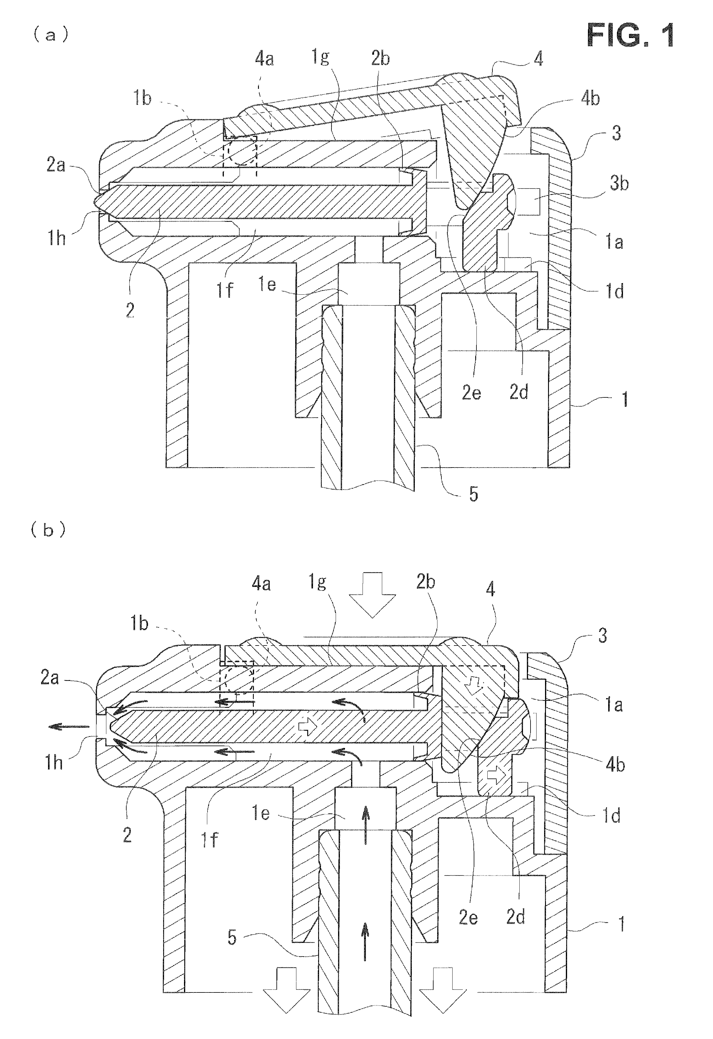
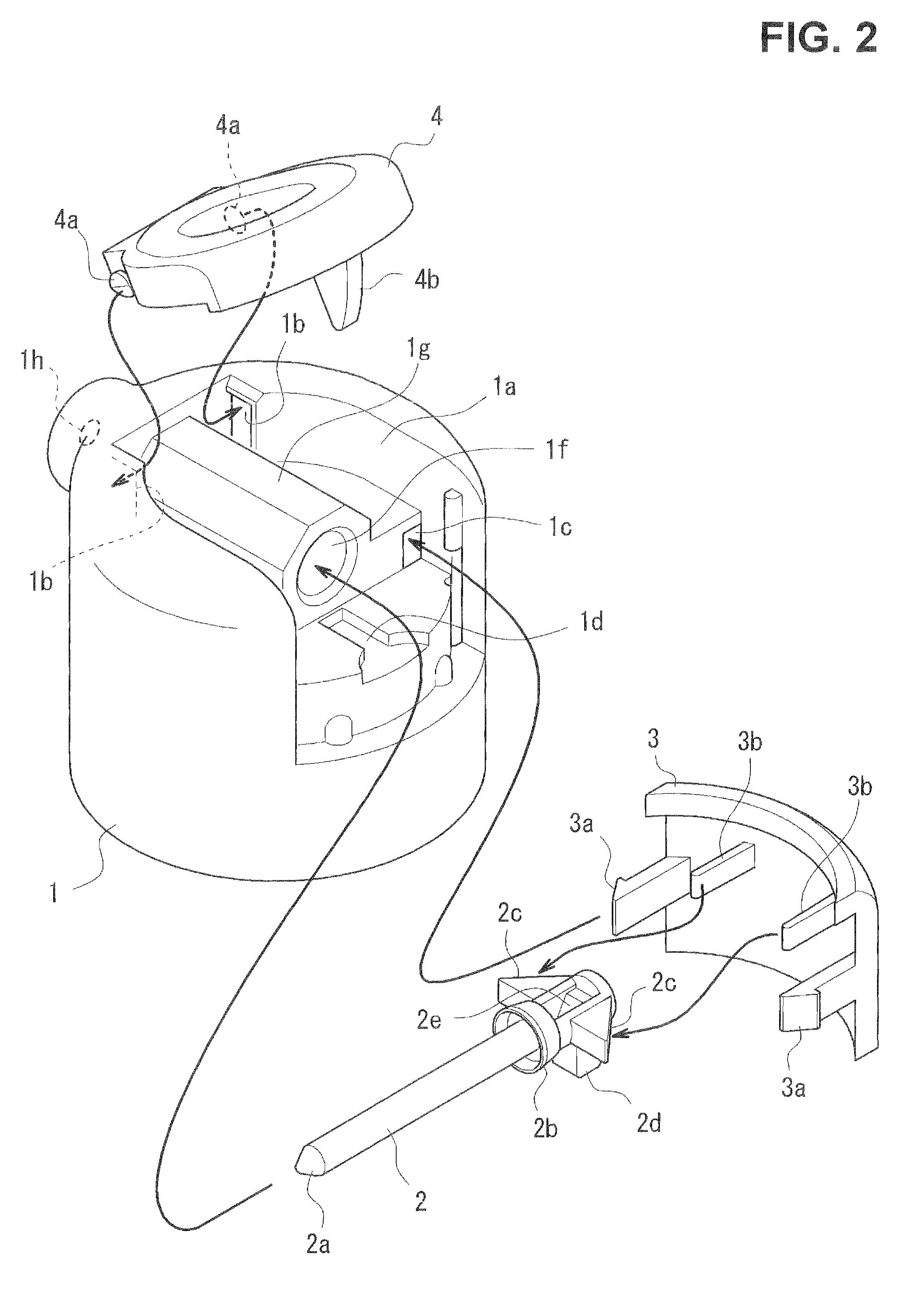
[0107]An assembling procedure of the tip-stop mechanism illustrated in FIGS. 1 and 2 is as follows, for example.[0108](31) The needle valve 2 is loaded to the longitudinal passage 1f of the spout 1 from the rear thereof.[0109](32) After the loading of the needle valve, a pair of the leg parts 3a of the peripheral wall rear cover 3 are put into a pair of the recessed parts 1c of the spout 1 from the backward and engaged therewith.[0110](33) A pair of the rotary shafts 4a of the operation lever 4 are immersed into a pair of the recessed parts 1b on the front side of the spout 1.[0111](34) The spout 1 is fitted to the stem 5.
[0112]Upon the pair of the legs 3a of the peripheral wall rear cover 3 being inserted into the recessed part 1c of the spout 1, the legs first abut along its tapered surface on the rear spout internal peripheral surface of the recessed part and go forward resisting own elastic force while displacing inwardly a little, respectively. Once the rear end of the tapered ...
embodiment 2
[0131]Main differences between components in a tip-stop mechanism in FIG. 3 and those in FIGS. 1 and 2 are as follows:[0132](51) A coil spring 15 is used instead of the leaf spring 3b in FIGS. 1 and 2.[0133](53) pair of grooves 1d are formed in a rear flat plane of the spout 11 for respectively guiding a lower protruded part 12d of a needle valve 12.[0134](52) A sheath-shaped part 12c is formed at a rear end central part of the needle valve 12 for accommodating the coil spring 15.[0135](54) A pair of the lower protruded parts 12d guided to a groove part 11d of a spout 11 and a pair of receiving parts 12e for response to the operation lever.[0136](55) A pair of fractional part 14b abutting on the receiving parts 12e of the needle valve 12 are formed on the operation lever 14.
[0137]The restriction of the assembling procedure of the tip-stop mechanism is that the needle valve 12 is loaded to the longitudinal passage 11 of the spout 11 and the coil spring 15 is inserted into a sheath-sh...
embodiment 3
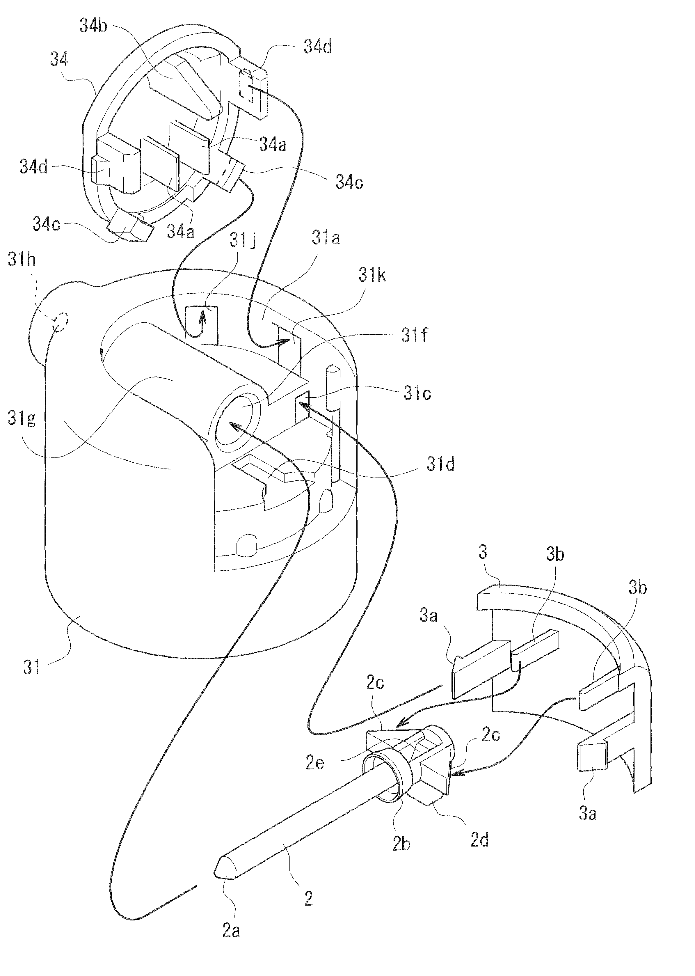
[0139]Main differences between components in a tip-stop mechanism in FIG. 4 and those in FIGS. 1 and 2 are as follows:[0140](61) A spout 21 and an operation lever 24 are integrally molded, and both members are connected by a hinge-shaped part 24a that is a turning base part of the operation lever 24.[0141](62) A needle valve 22 and a peripheral wall rear cover 23 are integrally molded via a pair of U-shaped leaf springs 23b. The needle valve 22 is movable frontally against the rear energizing force of the U-shaped leaf spring 23b in response to the turning operation of the operation lever 24 (setting operation of the actuation mode).[0142](63) The operation lever 24 includes a pair of protruded fractional parts 24c, 24d (tapered face plus engaging step) formed thereon and the spout 21 includes correspondingly a pair of guide recessed parts 21j, 21k. In the state of the tip-stop mechanism after assembled, the protruded fractional parts 24c, 24d are held by the guide recessed parts 21...
PUM
 Abstract
Description
Claims
Application Information
 - R&D
- Intellectual Property
- Life Sciences
- Materials
- Tech Scout
- Unparalleled Data Quality
- Higher Quality Content
- 60% Fewer Hallucinations
Browse by: Latest US Patents, China's latest patents, Technical Efficacy Thesaurus, Application Domain, Technology Topic, Popular Technical Reports.
© 2025 PatSnap. All rights reserved.Legal|Privacy policy|Modern Slavery Act Transparency Statement|Sitemap|About US| Contact US: help@patsnap.com


