Retractable utility knife

a utility knife and retractable technology, applied in the field of hand tools, can solve the problems of inconvenient replacement of blades, complex structure, inconvenient removal, etc., and achieve the effect of convenient storage and transportation, quick and convenient removal

Active Publication Date: 2009-11-05
OLYMPIA TOOLS INT
View PDF31 Cites 21 Cited by
  • Summary
  • Abstract
  • Description
  • Claims
  • Application Information

AI Technical Summary

Benefits of technology

[0006]It is another object of the invention to provide a retractable utility knife that is simple in construction and economical to manufacture.
[0008]It is yet another object of the invention to provide a retractable utility knife of the type under discussion that is easy and convenient to use.
[0010]It is still a further object to provide a utility knife as in the previous objects that has a slim profile and easy to store and transport.
[0011]In order to achieve the above objects, as well as others which will become apparent hereafter, a retractable utility knife in accordance with the present invention includes an elongate handle generally defining an axis. A blade holder is slidingly mounted within the handle for sliding movements relative to the handle along the axis between a retracted position and an extended position. The blade holder is configured for receiving at least a portion of a blade provided with one edge formed as a cutting edge and an opposing edge formed with a notch. A manually operable blade lock is formed on the blade holder and includes a release member rotatably mounted on the blade holder. The release member has a first portion projecting beyond the blade holder and positioned to be actuated by a finger of a user while holding the handle. A second portion of the release member is arranged to move with the first portion and moveable between a locking position in which the second portion is received within the notch of the blade and a releasing position in which the second portion is removed from and is positioned beyond the notch of the blade. Biasing means in the form of a spring is provided for normally rotating the release member to move the second portion to the locking position. In this manner, actuation of the release member by the finger of the user to overcome the biasing forces of the spring moves the second portion to the releasing position and the blade can be quickly and conveniently removed from the blade holder.

Problems solved by technology

However, it is not convenient to replace the blade.
However, the following problems exist.
The structure is complex; when replacing a blade, a user needs to release the lock member first and then rotate the top cover, which is complicated and inconvenient.

Method used


Image

  • Retractable utility knife
  • Retractable utility knife
  • Retractable utility knife

Examples


Embodiment Construction

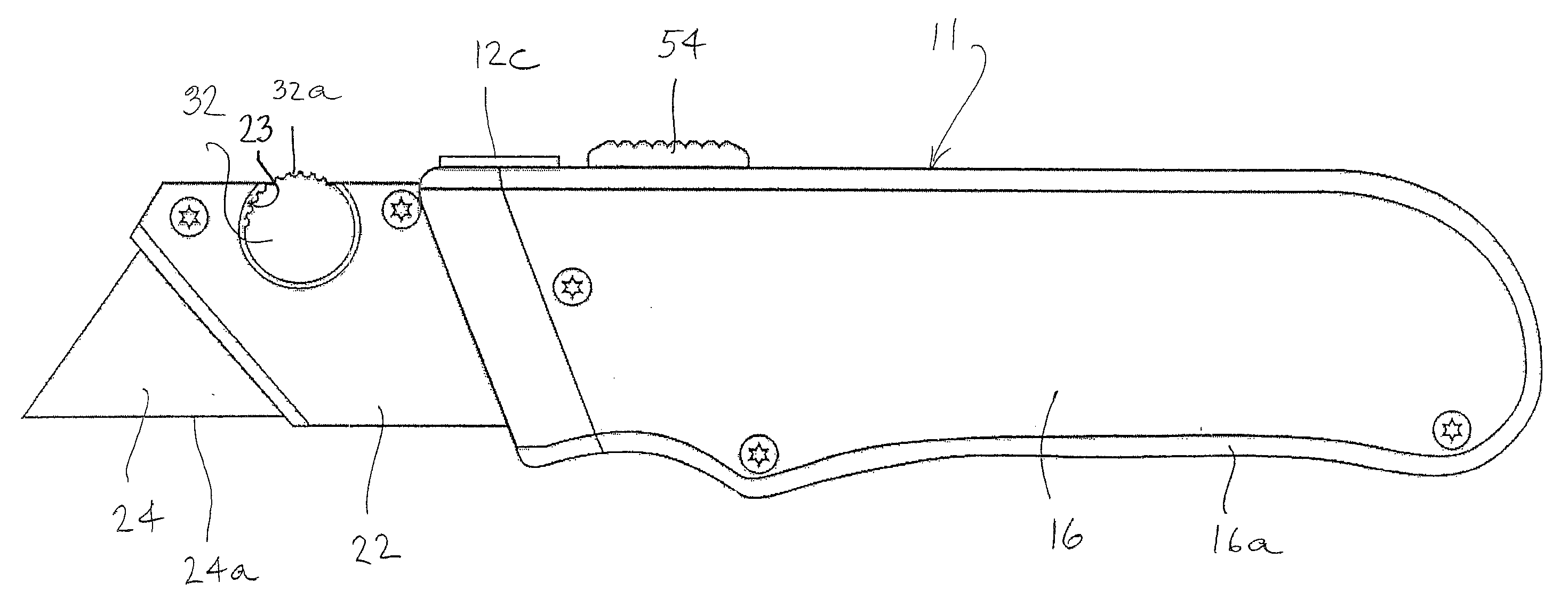
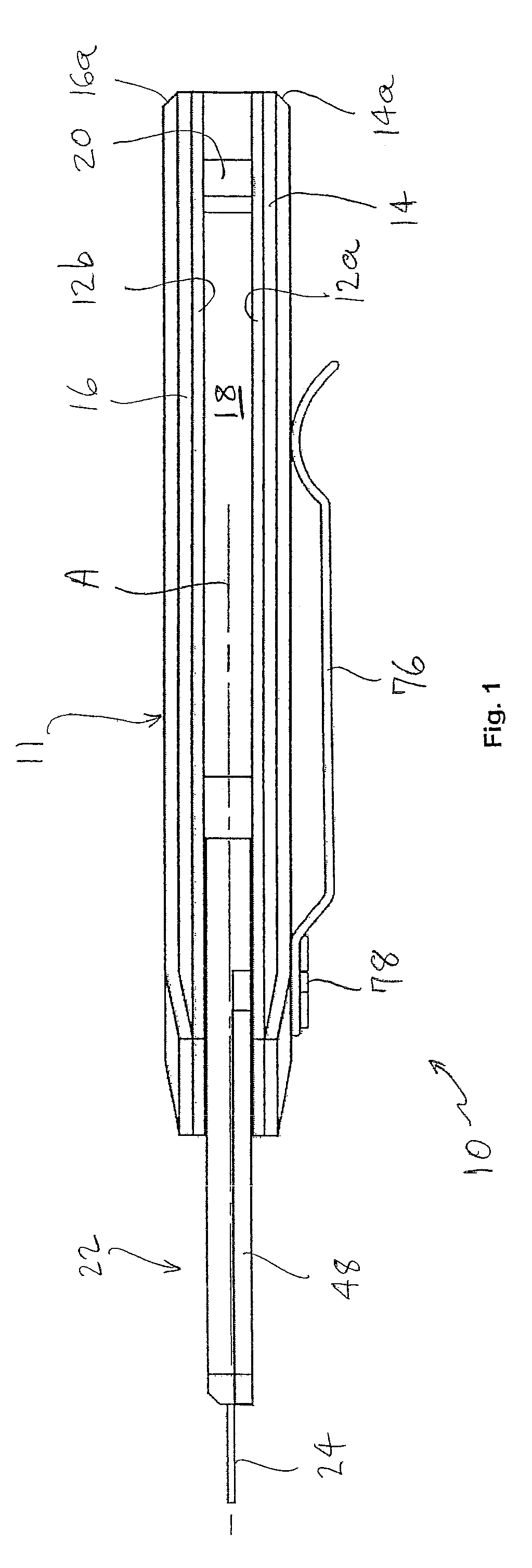
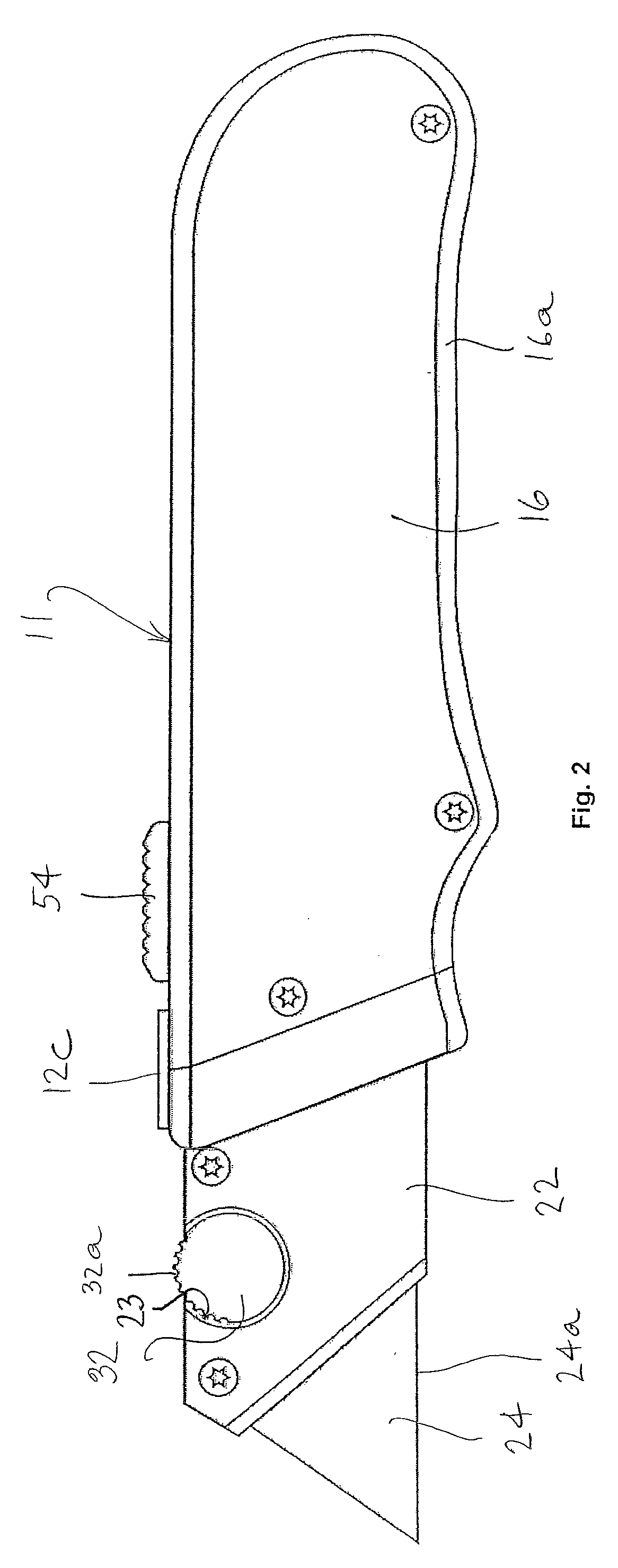
[0022]Referring know specifically to the Figures, in which identical or similar parts are designated by the same reference numerals throughout, and first referring to FIGS. 1-4, a retractable utility knife in accordance with the present invention is generally designated by the reference numeral 10.

[0023]The retractable utility knife 10 includes a handle 11, an exploded view of which is shown in FIG. 4. The handle 11 is generally elongate, as shown, and generally defines an axis A along its length direction. The handle 11 is preferably ergonomically configured to provide a comfortable grip by a user using the utility knife.

[0024]The handle 11 is formed of an inner frame 12 which includes spaced right and left plates or rails 12a, 12b separated a suitable or desired distance by means of a bridging strip 12c, shown in FIGS. 2 and 3. In the presently preferred embodiment, the plates or rails 12a, 12b are spaced approximately 0.25″ apart. The inner frame 12 is, in accordance with the pre...


PUM


Abstract

A retractable knife includes an elongate handle and a blade holder slidingly mounted within the handle for sliding movements between a retracted position and an extended position. The blade holder is configured for receiving. A manually operable blade lock is formed on the holder and including a release member rotatably mounted on the blade holder. The release member having a first portion projecting beyond the handle and positioned to be actuated by a finger of a user while holding the handle. A second portion is movable with the first portion between a locking position in which the second portion is received with a notch of a blade and a releasing position in which the second position is removed from the blade notch to a position outside the notch of the blade. A spring normally rotates the release member to move the second portion to the locking position. Actuation of the release member by the finger of the user to overcome the spring moves the second portion to the releasing position and releases the blade.

Description

BACKGROUND OF THE INVENTION[0001]1. Field of the Invention[0002]The present invention generally related to a hand tools, and more specifically to a retractable utility knife with a quick release blade mechanism.[0003]2. Description of the Prior Art[0004]Conventional utility knives have various types of structures including fixed, foldable and retractable. They are generally used to cut paper, fabric, and leather. The Chinese Patent Application No. 93208241.6 (Publication Date: Jun. 22, 1994) disclosed “a retractable rope-cut utility knife”, in which a blade stored in a handle is extended out step by step by moving a slider. However, it is not convenient to replace the blade. The Chinese Patent Application No. 03223149.0 (Publication Date: Dec. 24, 2003) disclosed “a combined utility knife”. It is convenient to replace a blade by arranging the blade in a groove of the handle assembly and using a top cover in connection with a lock member. However, the following problems exist. The st...

Claims


Application Information

Patent Timeline
Patent Type & Authority Applications(United States)
IPC IPC(8): B26B3/06B26B29/02
CPCB26B1/08B26B5/001
Inventor DE, HUANG YUAN
Owner OLYMPIA TOOLS INT
Why Eureka
Try Eureka