
Signal conversion device, radio frequency identification (RFID) tag, and method for operating the RFID tag

Inactive Publication Date: 2009-10-29
NAT TAIWAN UNIV
View PDF13 Cites 25 Cited by
  • Summary
  • Abstract
  • Description
  • Claims
  • Application Information

AI Technical Summary

Benefits of technology

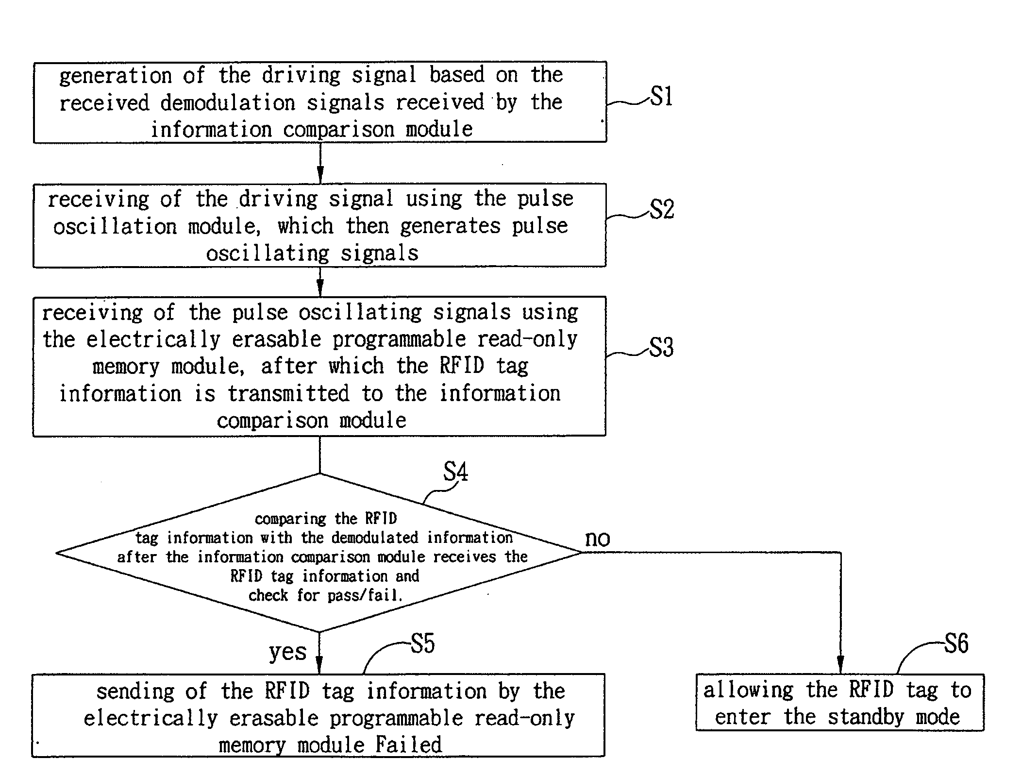
[0042]In addition, based on the above-mentioned RFID tag and the method for operating the same, after the RFID tag receives the RE signals, the signal demodulation module is employed to generate the demodulation signal. Comparison is performed based on the demodulation information and the information saved in the RFID tag. If the comparison is matched, the RFID tag will send the tag information to the reading device using a wireless transmission means, otherwise, the RFID tag is forced into the standby mode. The present invention discloses the RFID tag and the method for operating the same, thereby providing a simple, correct, and fast RFID tag circuit design, so as to significantly lower the manufacturing cost of the RFID and raise the possibility of commercialization of the passive RFID tag.

Problems solved by technology

However, BPSK signal format is more complex, thus it is more complicated to decode the BPSK signal to obtain the baseband digital information contained therein.
However, to a simple passive RFID tag circuit that is unable to use the microprocessor for demodulation, a low-cost and power-saving BPSK signal conversion device must be designed to extract the baseband digital information contained in the BPSK signal.
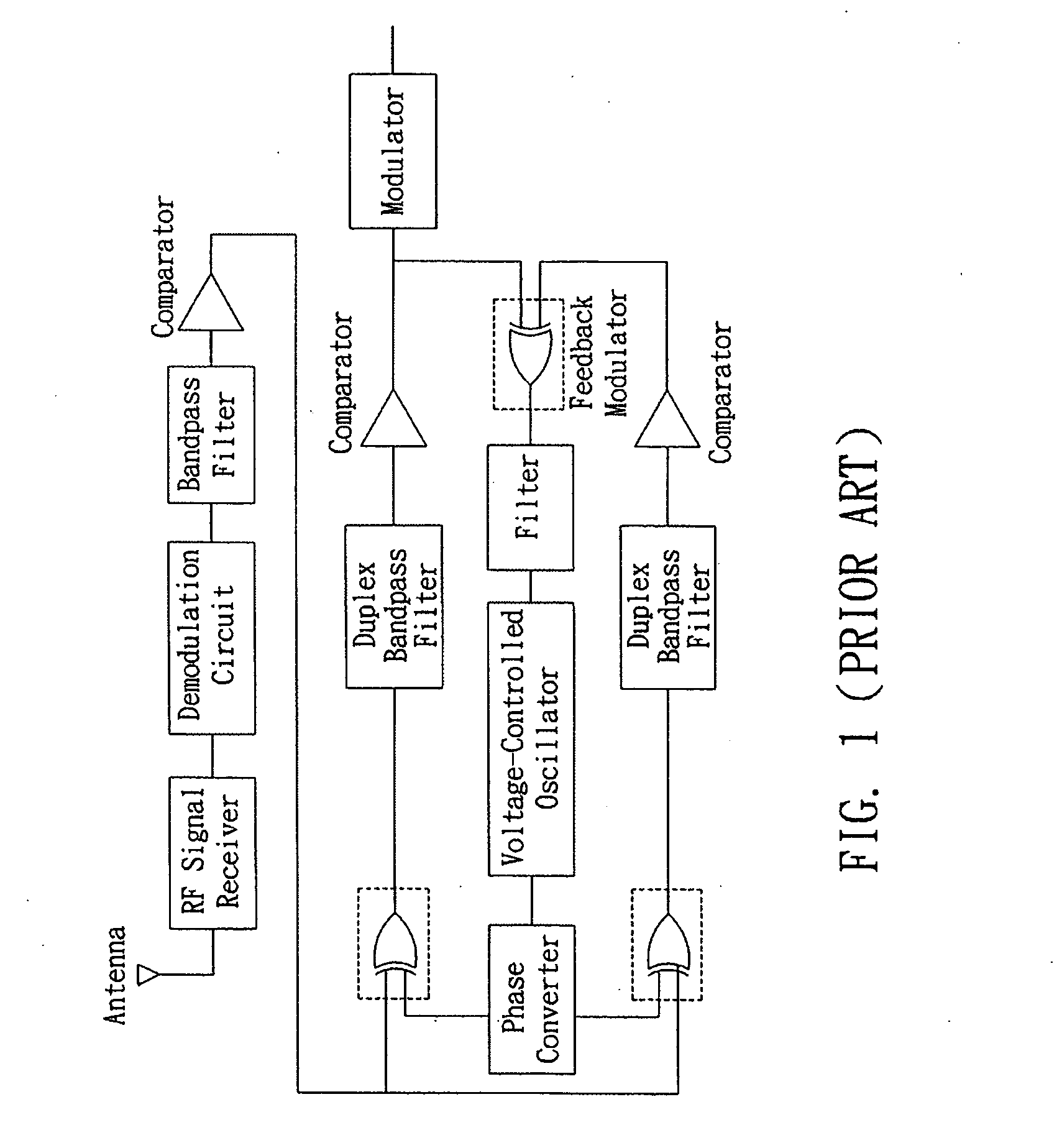
However, the problem of demodulation error often occurs in such circuit structure, a data decoder must be used to compensate the demodulation signal, or even worse, a microprocessor is sometimes needed to perform the signal compensation algorithm.
Therefore, such a circuit structure may have the advantage of circumventing analog components but it increases the design complexity.
In addition, lowering the manufacturing cost of the passive RFID tag to the level appropriate for mass production is an issue worth discussing in the event that the wireless RFID system is promoted such that it replaces the current bar code system for use in the inventory tracking or product identification management systems.
Sometimes, a microprocessor must be used to run the algorithm, and thus the manufacturing cost is increased, which impedes the progress of replacing the current bar code ID management system.

Method used


Image

  • Signal conversion device, radio frequency identification (RFID) tag, and method for operating the RFID tag
  • Signal conversion device, radio frequency identification (RFID) tag, and method for operating the RFID tag
  • Signal conversion device, radio frequency identification (RFID) tag, and method for operating the RFID tag

Examples


Embodiment Construction

[0059]The following illustrative embodiments are provided to illustrate the disclosure of the present invention, these and other advantages and effects can be apparently understood by those in the art after reading the disclosure of this specification.

[0060]The present invention can also be performed or applied by other different embodiments. The details of the specification may be on the basis of different points and applications, and numerous modifications and variations can be devised without departing from the spirit of the present invention.

[0061]FIG. 3a illustrates a block diagram of the signal conversion device of the present invention. As shown in the diagram, a signal conversion device of the present invention includes: a signal distribution module 11, a first injection-locked cross-coupled oscillation module 121, a second injection-locked cross-couple oscillation module 122, a first differential amplification module 131, a second differential amplification module 132, and ...


PUM


Abstract

A signal conversion device, a radio frequency identification (RFID) tag, and a method for operating the RFID tag. The RFID tag has an electrically erasable programmable read-only memory module for storing RFID tag information and transmitting the RFID tag information; an information comparison module coupled to the electrically erasable programmable for receiving the RFID tag information and demodulation information, comparing the RFID tag information with the demodulation information, and generating a driving signal; and a pulse oscillation module coupled to the information comparison module for receiving the driving signal, and transmitting pulse oscillating signals to the electrically erasable programmable read-only memory module, so as to allow the electrically erasable programmable read-only memory module to transmit the RFID tag information.

Description

BACKGROUND OF THE INVENTION[0001]1. Field of the Invention[0002]The present invention relates to a signal conversion device, and more particularly to a wireless RF signal conversion device. The present invention relates to a radio frequency tag and the method for operating the same, and more particularly to a radio-frequency tag having the information for comparing digital logic and the method for operating the same.[0003]2. Description of Related Art[0004]The Radio-Frequency Identification (RFID) system has been recognized as a major development trend in the electronic industry, and the system is designed based on different modulation methods such as OOK (100% ASK), x % ASK, FSK, PSK and FHSS as required, thereby achieving different signal transmission formats.[0005]In particular, BPSK is a signal modulation mode that has an uninterrupted transmission capacity, a high data rate, and a noise immunity property; therefore it has been widely used in various techniques involving wireles...

Claims


Application Information

Patent Timeline
IPC IPC(8): H04Q5/22H03C1/00
CPCH04Q9/00H03B5/1231H03B5/1215H04Q2209/47H03D7/12H03D2200/0005H03D3/24H03B5/1243H03B2200/0074
Inventor LIU, CHI-ENKIANG, JEAN-FU
Owner NAT TAIWAN UNIV
Learn More