
Method and arrangement in connection with a brake chopper

a technology of brake chopper and control method, which is applied in the direction of stop arrangement, dynamo-electric converter control, motor/generator/converter stopper, etc., can solve the problems of increasing the cost, affecting the control of the and the structure of the fig. 3 with dc current measurement from the dc intermediate circuit, etc., to achieve cost-effective and accurate measurement of inverter bridge current, accurate control of the control electrical machine control

Active Publication Date: 2009-10-29
ABB (SCHWEIZ) AG
View PDF7 Cites 11 Cited by
  • Summary
  • Abstract
  • Description
  • Claims
  • Application Information

AI Technical Summary

Benefits of technology

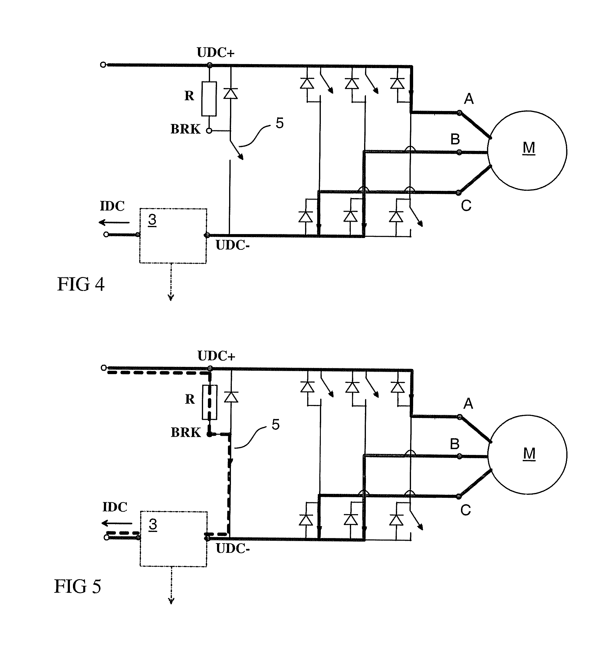
[0016]An advantage of the method and apparatus of the invention is that the measurement of inverter bridge current can be made accurately by using DC current measurement even if the current measurement is carried out from the DC side of the brake chopper.
[0017]The invention allows using a cost effective and accurate current measurement in a frequency converter, which further enables accurate control of the controlled electrical machine. The invention is especially suitable to be used in connection with a modulation scheme where only one zero vector is used in each control period.

Problems solved by technology

In low-cost and smaller size frequency converters the additional cost of a rectifier which could feed power back to the supplying network would increase the costs and make the converter less appealing.
It has been noticed that the structure of FIG. 3 with DC current measurement from the DC intermediate circuit is problematic.
This current is summed with the motor phase current and the measurement does not give the desired value of phase current.
The resistance can be identified during start-up of the converter, but since the resistance is dependent on the temperature, the identified value would not necessarily be valid during operation.
This would directly distort the calculated result and render it useless.
Another problem relating to DC current measurement and subtraction of braking current from the measured DC current is the saturation of the current measurement device.
Since the output of the operational amplifier cannot be higher than its positive operational voltage, a risk of saturation is evident.
In this kind of situation the subtraction of braking current would be carried out from already distorted measurement, and the end result would also be erroneous.

Method used


Image

  • Method and arrangement in connection with a brake chopper
  • Method and arrangement in connection with a brake chopper
  • Method and arrangement in connection with a brake chopper

Examples


Embodiment Construction

[0025]According to the present invention, an output voltage is formed with the inverter bridge to a load that is connected to the output of the inverter bridge. The inverter bridge is usually used as the output stage of a frequency converter. Inverter bridges can, however, be also connected directly to a DC source without an inverter bridge specific rectifier part.

[0026]The inverter bridge generates output voltage that has an average voltage corresponding to the desired voltage. Typically output voltage is controlled to the desired voltage within a control period. The control period is a time period in which the time average of the inverter output voltage corresponds to the desired value. FIG. 6 shows one example of modulation of output switches.

[0027]In the example of FIG. 6 the states of output phases A, B, C are shown as either high or low. In the high state the respective phase output is connected to the positive voltage of the intermediate circuit and in the low state the phase...


PUM


Abstract

A method of controlling a brake chopper and a control arrangement, the brake chopper being connected between the positive and the negative rails of an intermediate voltage circuit feeding an inverter bridge, wherein current measurement means are arranged between a DC voltage source and the brake chopper and adapted to measure DC current flowing in the intermediate voltage circuit, which method comprises steps of forming with the inverter bridge an output voltage to a load connected to the output of the inverter bridge, determining a time instant when the DC current of the intermediate circuit is sampled, and preventing the use of the brake chopper at the determined time instant.

Description

FIELD OF THE INVENTION[0001]The present invention relates to controlling a brake chopper, and more particularly to a method and an arrangement in which a brake chopper is used in connection with DC-current measurement of an inverter bridge.BACKGROUND OF THE INVENTION[0002]Brake choppers are commonly used in frequency converters for dissipating regenerated energy that cannot be fed back to the supplying network. For example in a case where a motor supplied by a frequency converter with a DC voltage intermediate circuit is rotated by the load, the motor acts as a generator and feeds power back to the supply. When the rectifying bridge of the frequency converter is not configured to feed the regenerated power back to the network, the voltage of the intermediate circuit starts to increase.[0003]When the voltage of the intermediate circuit has increased to a limit which is higher than the nominal voltage of the intermediate circuit, the brake chopper, which is a circuit comprising a cont...

Claims


Application Information

Patent Timeline
Patent Type & Authority Applications(United States)
IPC IPC(8): H02P3/22
CPCH02P3/22H02P27/12H02P6/24
Inventor VIITANEN, TEROLEPPANEN, ORA VELI-MATTI
Owner ABB (SCHWEIZ) AG
Learn More